i get a big voltage swing at the CF output
if i want a line level output, what's the best option : voltage divider before or after the CF ?
thanks !
if i want a line level output, what's the best option : voltage divider before or after the CF ?
thanks !
Place attenuating circuitry in the grid circuitry of the CF. You definitely don't want to compromise load driving capability.
Leave the 250K pot where you had it and the wiper of the 250K pot can go to the grid of the CF through a small coupling cap.
Well, it's all good,
waiting for two 1uF caps to get more bass and it will be okay 🙂
heaters are elevated to 75VDC, cathode sits at 150VDC that's about 5ma (33k +1k cathode resistor), waiting for a new 12AU7 this one is a bit used
waiting for two 1uF caps to get more bass and it will be okay 🙂
heaters are elevated to 75VDC, cathode sits at 150VDC that's about 5ma (33k +1k cathode resistor), waiting for a new 12AU7 this one is a bit used
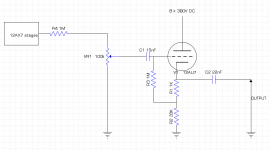
So, here's the full schematic
I have some questions regarding the attenuation before the CF
I need to atenuate a LOT because i want a line level after the CF that's about 2V peak to peak
Even with 1M and a 100k pot, i still get about 8V peak to peak
Should i put a bigger R4? Or make VR1 smaller ?
I have some questions regarding the attenuation before the CF
I need to atenuate a LOT because i want a line level after the CF that's about 2V peak to peak
Even with 1M and a 100k pot, i still get about 8V peak to peak
Should i put a bigger R4? Or make VR1 smaller ?
Attachments
Hello!
back on this project
It's working great with a 1uF/250V coupling cap at the output
BUT... i get DC at the output when nothing's connected to it and when i power on and off the circuit
Seems the capacitor holds its charge and gives it back..
1uF is enough to zap your finger, i don't think it's great for the sound card either.
Any idea ?
I tried a 1meg after the coupling cap to ground, even 100k, but i still get some DC at startup and shutdown - and it might not be so good regarding impedance ?
Seems the capacitor is faulty.Seems the capacitor holds its charge and gives it back..
You have measurable DC voltage at the output of the capacitor with a 100K resistor from the output of the cap to ground? How much DC voltage?
cap is not faulty. That's normal behavior when charging / discharging... What i would need, is a way to limit that 🙂
With a 1m from capacitor output to ground, i get a rising DC to 50V and then it goes back to 0 at power on ; and then a rising to -50VDC and back to 0 at power off
With a 1m from capacitor output to ground, i get a rising DC to 50V and then it goes back to 0 at power on ; and then a rising to -50VDC and back to 0 at power off
Well, tried 10k, it seems to do the job, i only get a 1.5V spike at startup and shutdown, and sounds seems good !Try 10K instead of 1M.
Just to learn, what is the new output impedance of the circuit with that 10k after the coupling cap ?
Output impedance is approximately 1/gm, we could round up and call it 500 ohms.
You will need to run enough standing current through the cathode follower to drive your intended load plus that 10K resistor. I am way too lazy to go figure out how much current you're actually running, but it looks like more than 5mA, and that's plenty!
You will need to run enough standing current through the cathode follower to drive your intended load plus that 10K resistor. I am way too lazy to go figure out how much current you're actually running, but it looks like more than 5mA, and that's plenty!
thanks,Output impedance is approximately 1/gm, we could round up and call it 500 ohms.
You will need to run enough standing current through the cathode follower to drive your intended load plus that 10K resistor. I am way too lazy to go figure out how much current you're actually running, but it looks like more than 5mA, and that's plenty!
the load will be a sound card (10k impedance)
yes i get around 5ma - i will measure it tomorow
thanks !
I was also too lazy to get more specific about some basic analysis.
You have your cathode resistor in parallel with that resistor after the cap in parallel with whatever load you are driving (10K from your sound card). That sets the AC load for the cathode follower. That's about 4300 ohms, which is 10x your output impedance, so that's great.
The problem can arise though when you don't run enough current. Say that total is still 4300 ohms and you're running a 12AX7 at 1mA. Now you're going to have a tough time getting a lot of output (~2.5V RMS or so) because current availability from the cathode follower is so low. You can swing a max of +/-1mA, and in reality it will be a little less than that. If you're up around 5mA, this limitation will be well over 10V RMS.
- Home
- Amplifiers
- Tubes / Valves
- add a line out to a tube preamp, with one triode and one transformer per channel