Hi,
Renovating some old speakers (complete redesign og baffle and crossovers) and I have come across a weird issue. When measuring the impedance of the woofer the Fb of the box is way of the one calculated.
Data:
Driver: Scan-Speak W30/4558T00 (https://www.scan-speak.dk/datasheet/pdf/30w-4558t00.pdf)
Vb: 83L (not optimal for the woofer but it is all I got to work with)
Pd: 70mm
Plength: 290mm
Fb: 20hz
Measured Fb: 32hz
There is some old dampening material in the cabinet (10mm green wool) that I dont want to remove therefore the Vb might be marginaly larger but if anything that should yield a lower than calculated Fb?
Any suggestions outside of airleaks? 😱
The cabinet is well built with brand new seals around the drivers and the front baffle so Im out of ideas.
If the reduction of cabinet volume from dampening material, speaker and port volume are not allowed for, the Vb is smaller than you figured. Smaller Vb requires a longer port to achieve the same Fb. As an extreme example, reducing Vb by 1/2 would require the port to be almost twice as long for a 20 Hz tuning.When measuring the impedance of the woofer the Fb of the box is way of the one calculated.
Vb: 83L (not optimal for the woofer but it is all I got to work with)
Pd: 70mm
Plength: 290mm
Fb: 20hz
Measured Fb: 32hz
There is some old dampening material in the cabinet (10mm green wool) that I dont want to remove therefore the Vb might be marginaly larger but if anything that should yield a lower than calculated Fb?
Any suggestions outside of airleaks? 😱
Vb computation errors could account for some of the discrepancy, impedance measurement could account for some. Try checking the Fb visually with a sine wave, excursion should be at minimum at Fb.
Art
If the reduction of cabinet volume from dampening material, speaker and port volume are not allowed for, the Vb is smaller than you figured. Smaller Vb requires a longer port to achieve the same Fb. As an extreme example, reducing Vb by 1/2 would require the port to be almost twice as long for a 20 Hz tuning.
Vb computation errors could account for some of the discrepancy, impedance measurement could account for some. Try checking the Fb visually with a sine wave, excursion should be at minimum at Fb.
Art
Hi Art and thanks for the reply.
The Vb is the volume excluding the dampening material so if that material (seems like thight woven felt) is "open" the Vb would be closer to 92 litres. I will try to do the physical check but the speakers is located a few hrs drive away so I wont be able to do it asap.
Is there anything else that comes to mind?
I can add that even lengthening the port to over 700 mm didn't lower the Fb by more than a 4-5 hz.
Thanks!
-F
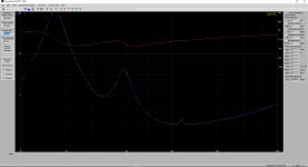
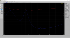
Here are two of the measurements both in text and png.
Both of these cabinet tunings should yield a Fb of >20Hz according to both manual calculation and use of WinISD/Speakerbuilder Pro 2.0 (Speakerbuilder Pro 2.0)
Is it possible that DATS is so inaccurate?
-F
Both of these cabinet tunings should yield a Fb of >20Hz according to both manual calculation and use of WinISD/Speakerbuilder Pro 2.0 (Speakerbuilder Pro 2.0)
Is it possible that DATS is so inaccurate?
-F
Attachments
What are the dimensions of the cabinet, and the thickness of the material that you used to build them?
The port looks very lossy. Is there anything blocking air flow to/inside the port?
Chris
Hi,
Not that I can think of although I didn’t feel much movement from the port regardless of length even at quite high spl.
The port is buildt with a 90 degree kne to allow for the port length. If it has any relevance the cabinet internal dimensions are H:770 W:470 D:230.
-F
What are the dimensions of the cabinet, and the thickness of the material that you used to build them?
I haven't measured it since its an old DIY speaker (SEAS Kit from the early 70's) that my father built way back. Refurbishing them for him now.
If I had to make a educated guess the outer dimensions are close to 900 x 600. Built of 19mm plywood lined inside with plasterboard and wool felt (as mentioned above).
Baffle is 32mm thick sandwiched MDF and ply.
It is not an ideal enclosure, but this build was all about keeping the appearance of the old speakers and try to make them sound good at the same time (open for trade offs).
-F
In that case, I suggest confirming the internal dimensions, to ensure that you're using the correct figure for the net internal volume in your calculations.
Also, as another poster mentioned, the impedance curve suggests that the cabinets are very lossy. This could be caused by using a lot of stuffing in a vented enclosure.
Also, as another poster mentioned, the impedance curve suggests that the cabinets are very lossy. This could be caused by using a lot of stuffing in a vented enclosure.
In that case, I suggest confirming the internal dimensions, to ensure that you're using the correct figure for the net internal volume in your calculations.
Also, as another poster mentioned, the impedance curve suggests that the cabinets are very lossy. This could be caused by using a lot of stuffing in a vented enclosure.
Ok thanks for that input.
I will remove the wool felt the cabinet is lined with next time I work on them and do new calc/measurements. Already removed all the acoustic wool they where stuffed with (used to be a closed cab) but I guess that might not be enough then.
-F
Hmm, HR calcs 19.8 Hz and have to reduce Vb to 31.4 L for 32 Hz Fb, so 'sounds' like a leak to me.
GM
GM
Hmm, HR calcs 19.8 Hz and have to reduce Vb to 31.4 L for 32 Hz Fb, so 'sounds' like a leak to me.
GM
Well that was my first thought as well but I can hardly understand where that leak is since every permanent corner is sealed with flexible construction glue and screws. The front baffle which is removable has a 20 mm rubber foam seal behind it and screws with c/c 140 mm 15 mm from the edge.
As I understand from the other posts and reading about acoustics is that adding more dampening to a woofer cabinet moves it towards a closed cabinet defeating the purpose of the port design.
I guess a leak or heavy dampening would give more or less the same result?
-F
Right, it damps vent action, raising F3, lowering Fb, i.e. increasingly a more sealed like roll off response. A leak OTOH raises F3, Fb, hence my belief it's a leak. Some stuffing results: https://www.ranger5g.com/forum/attachments/box-builder-fill-er-up-pdf.35156/
FWIW, most hard to find leaks are at the driver, etc., mounting points with over torquing a common problem and/or poor fitting hardware.
GM
FWIW, most hard to find leaks are at the driver, etc., mounting points with over torquing a common problem and/or poor fitting hardware.
GM
Thank you everyone for feedback and tips.
I was finally able to work on the speakers again and managed to improve the measurements by re-torquing both the speaker front and driver. I chose not to remove the thin felt padding of the enclosure as it is glued on plasterboard some 50 years ago and I dont wanna mess with it.
It is still not at the calculated Fb but much closer.
I have never thought of leaks around a driver as it never seemed like a problem with smaller drivers. This is my first 12" woofer project.
Now it is of to do freq response measurements (trying to acquire a turning table) and start designing the new crossovers.
Cheers
Quick update:
Exchanged the screws used on the frontpanel to ones with 32mm straight before the thread and also did a 6mm drill plunge about 5mm into the back of the frontplate. Re tightened and voila, Fb dropped to 17.5Hz (bit low for my taste).
I found the leaks by using the signal generator in REW and run 25hz at a decent level.
I have used a 90 degree knee pipe on the baffle to accommodate for the port lengths as the cabinet is quite shallow.
Does this add any "factor" to the port tuning?
I used the mean length of the knee and added a short straight pipe to get the 29cm calculated. But as I know a tad about aerodynamics I also know that changes in direction will change the pressure and speed of fluids.
-F
Not surprised there was hardware leaks, me and some others have had leaks around threaded inserts, T-nuts.
Right: Objectives_template
FWIW, some different ways to measure horn bends with 71.4 cm being most accurate:
GM
Right: Objectives_template
FWIW, some different ways to measure horn bends with 71.4 cm being most accurate:
GM
Attachments
- Home
- Loudspeakers
- Subwoofers
- Measured Fb missmatch against calculated.