Hello guys
I have an Class T US Amps PT-800 rev.2.
Amp works but pushed a little bit harder and it cuts out audio output.
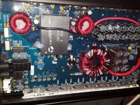
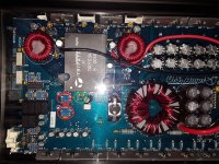
There is a green diode (in green circle) near the Tripath's chip , it goes off when the amp cuts its output. Power light stays on, no protection.
There are two potentiometers near the chip (in red). They have been messed around by the previous owner. What are these for and how to set them up correctly ?
I do not have the schematics and in owners manual there is nothing about those two potentiometers.
Any help would be greatly appreciated.
I have an Class T US Amps PT-800 rev.2.
Amp works but pushed a little bit harder and it cuts out audio output.
There is a green diode (in green circle) near the Tripath's chip , it goes off when the amp cuts its output. Power light stays on, no protection.
There are two potentiometers near the chip (in red). They have been messed around by the previous owner. What are these for and how to set them up correctly ?
I do not have the schematics and in owners manual there is nothing about those two potentiometers.
Any help would be greatly appreciated.
Attachments
The pots may be DC offset.
The diode may be the same as LED2 in the following diagram:
http://www.bcae1.com/temp/clarion - dpx1001.2.pdf
The diode may be the same as LED2 in the following diagram:
http://www.bcae1.com/temp/clarion - dpx1001.2.pdf
The pots may be DC offset.
The diode may be the same as LED2 in the following diagram:
http://www.bcae1.com/temp/clarion - dpx1001.2.pdf
Yeah maybe they are DC offset.
LED2 at the provided diagram is for one ohm operation mode. My amp is not capable of driving one ohm loads.
My guess is that this green diode is for the operation of the Tripath chip itself. I draw my conclusion from when there is output it's light up, when the output is being cut off it goes off too.
And without schematics I can't trace and understand how the overcurrent protection works... I know in class D there are precise low ohm resistors but in class T... ?! 😕😕😕
PS:Oh sorry I forgot it's PIC controlled so there is no way i can rework the protection circuit...
Last edited:
This wasn't meant to be a perfect schematic.
It doesn't have to be one ohm. It could just be over-current or protection.
Maybe someone else will have something.
It doesn't have to be one ohm. It could just be over-current or protection.
Maybe someone else will have something.
Sorry, If was rude, it wasn't purposel.
Thanks for the help Perry, You always help a lot.
I will look out for the pinout of the TA0103A tripath chip online too see if i find anything
Thanks for the help Perry, You always help a lot.
I will look out for the pinout of the TA0103A tripath chip online too see if i find anything
Okay the datasheet for the TA0103A is going to take hours to read.
But if i'm being right there should resistors as these in my amp too. These are the overcurrent sensing resistors, aren't they ? 😕
But are these integrated in the chip itself or they are board mounted ?
But if i'm being right there should resistors as these in my amp too. These are the overcurrent sensing resistors, aren't they ? 😕
But are these integrated in the chip itself or they are board mounted ?
Attachments
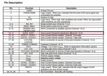
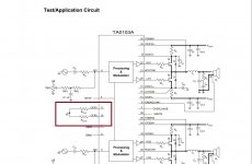
The current sensing resistors are Rs. The resistors you indicate appears to set the threshold.
So lowering or increasing the value of the Rocr1 and Rocr2 would affect the threshold point ?
I will have to reverse engineer my amp...
- Home
- General Interest
- Car Audio
- Class T issues US Amps PT-800 rev.2