Not sure which forum this should go in. I am waiting for parts to arrive for a 3255 build. Just a Meanwell PSU, 3e audio 3255 board and a Khadas Tone Board. I was planning on having a relay to switch between the analog output of the DAC and the analog RCA inputs and using a DACT stepped attenuator.
I will have a separate 5v/12v SMPS for the DACT so can add a RPI later to turn it into a streamer if i want.
The only other thing I could wish for is the ability to plug in a set of headphones when the Mrs/kids are sleeping.
It seems that having a separate amp for this is the easiest way to go as headphones + class D amps don't seem to mix due to the common ground on the headphones.
I have been looking at the CMoy type amps but they are designed for battery use and maybe not the best for what I want. I am impressed with people's opinions on the OPA1622 or OPA1688 but I am really a noob here and need a design that I can easily follow without having to design my own PCBs etc. It doesn't need to be as small as a CMoy. Basically I will have access to 5v or 12v in my build (as well as 48v) from a clean SMPS and would like to be able to have a switch to swap between the 3255 and the headamp or have it switch over when plugging the TRS in. My headphones are 32ohm.
Can anyone sugggest an easy way of doing this?
Thanks,
Mark
Have you tried AC coupling the headphones to just one side of the amplifier speaker output. 470uF 63v cap for starters.
Add a series resistor (trial and error... try say 100 ohm begin) and a shunt resistor (say 10 ohm) across each headphone. Easy and simple if it works OK.
If you make it permanent then think about the wattage needed for the series resistor, probably a couple of watts at a guess.
Add a series resistor (trial and error... try say 100 ohm begin) and a shunt resistor (say 10 ohm) across each headphone. Easy and simple if it works OK.
If you make it permanent then think about the wattage needed for the series resistor, probably a couple of watts at a guess.
With a board like this running alogside the 3255 board, would I just take off the pot and wire it up to the main pot with the 3255?
Where would I switch between the amps? I was already going to have a selector switch to go between RCA inputs and the DAC.
Also do these board need any parts replaced or are they good to go. Certainly seems an attractive option as it is littl emore than the cost of the op amp alone.
Have you tried AC coupling the headphones to just one side of the amplifier speaker output. 470uF 63v cap for starters.
Add a series resistor (trial and error... try say 100 ohm begin) and a shunt resistor (say 10 ohm) across each headphone. Easy and simple if it works OK.
If you make it permanent then think about the wattage needed for the series resistor, probably a couple of watts at a guess.
I appreciate the advice here. Even this is a bit beyond my basic knowledge but i'll try to get my head around it.
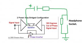
OK, so the speaker connects between two amplifier outputs which allows much more voltage swing to the speaker... so more power for a given supply voltage. The two outputs are electrically 180 degrees out of phase.
As one goes 'up' in voltage, the other goes 'down'.
This means each speaker terminal, the plus and minus, are not ground referenced but both are 'live', both have DC voltage present.
Each terminal carries the same audio.
If you add a capacitor to feed the headphone you block the DC, just like old school normal amps.
A series resistor limits the power the headphone can see, just like any amp with a headphone socket.
A low value resistor across the headphone socket feed gives the phones a low impedance feed.
- Home
- Amplifiers
- Class D
- Adding a op amp headphone amp to my 3255 build.