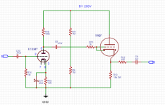
I am building a Pre-amp / buffer so I can run a ceramic cartridge turntable through some powered studio monitors I have. There is a impedance mismatch going on so after running through a 12a (*)7 I plan on using 12SQ7 tubes as Cathode followers on the output.
The CFs (Stereo) will be fixed biased by the two 1M resistors and the 12SQ7 has a diode I can use to protect the cathode to grid arcing before the heaters warm up and it should be reverse biased and OFF after that. That is part of the reason I chose the 12SQ7 plus it has a trans-conductance of about 1K for the low impedance output I need.
I would like to run this design by you all because I am not the experts you are. Does this look good? Any comments / advice would be appreciated.
Attachments
Sorry but the diode function won't work as expected, the diod needs a hot cathod to work,
and you need the diod when cathode is cold.
Use an 1n4147 instead from grid to cathod.
and you need the diod when cathode is cold.
Use an 1n4147 instead from grid to cathod.
My advice would be to remove the coupling cap and the two 1M resistors. Also add a resistor to ground after C9. I would also wonder why you'd need C10...
The other advice about using a silicon diode is spot on.
The other advice about using a silicon diode is spot on.
My advice would be to remove the coupling cap and the two 1M resistors. Also add a resistor to ground after C9. I would also wonder why you'd need C10...
The other advice about using a silicon diode is spot on.
The two 1M resistors is what sets the fixed bias, you think it would be better to just run it self biasing? What would the resistor after C9 do? Would it be a high value like a grid leak resistor?
Blaxshep,
If you want to squeeze every last performance drop out of a piezoelectric cartridge, buffer said cartridge right at the arm pillar with MOSFET voltage followers. Piezoelectric devices work best into extremely high impedances and very low capacitances. That's achieved by buffering as close to the cartridge as practicality allows.
BTW, that 1 MOhm value for R14 will interact badly with the 'X7 triode's high CMiller to roll HF info. off. 😡 100 KOhms is the safe max., for 'X7 grid to ground resistors. 100 Kohms as the load of a piezoelectric cartridge is (IMO) a dubious proposition. 🙁
If you want to squeeze every last performance drop out of a piezoelectric cartridge, buffer said cartridge right at the arm pillar with MOSFET voltage followers. Piezoelectric devices work best into extremely high impedances and very low capacitances. That's achieved by buffering as close to the cartridge as practicality allows.
BTW, that 1 MOhm value for R14 will interact badly with the 'X7 triode's high CMiller to roll HF info. off. 😡 100 KOhms is the safe max., for 'X7 grid to ground resistors.
100 Kohms as the load of a piezoelectric cartridge is (IMO) a dubious proposition. 🙁Blaxshep,
If you want to squeeze every last performance drop out of a piezoelectric cartridge, buffer said cartridge right at the arm pillar with MOSFET voltage followers. Piezoelectric devices work best into extremely high impedances and very low capacitances. That's achieved by buffering as close to the cartridge as practicality allows.
BTW, that 1 MOhm value for R14 will interact badly with the 'X7 triode's high CMiller to roll HF info. off. 😡 100 KOhms is the safe max., for 'X7 grid to ground resistors.
I was planning on using a Y7 or maybe a U7. Lower gain is lower CMiller effect right? Would that allow say a 220K or higher? which would be better for the cartridge? What is the impedance of a MOSFET? I am trying to use tubes. Could I use a Cap to roll off HF at the grid? I doubt the ceramic cartridge has a lot of HF? I'm using a NOS Astatic, not really high end.
Last edited:
The two 1M resistors give you 1/2 B+. You could also get that from the plate of the previous tube by directly coupling them. I didn't check where your AX7 plate voltage lands, but I'm sure you could set it close to 100V.
The resistor after C9 will prevent the 100V of DC voltage from appearing at the output jack when you don't have this connected to anything.
The resistor after C9 will prevent the 100V of DC voltage from appearing at the output jack when you don't have this connected to anything.
The two 1M resistors give you 1/2 B+. You could also get that from the plate of the previous tube by directly coupling them. I didn't check where your AX7 plate voltage lands, but I'm sure you could set it close to 100V.
The resistor after C9 will prevent the 100V of DC voltage from appearing at the output jack when you don't have this connected to anything.
I like that with setting plate voltage to 100V.
Wouldn't C9 prevent the DC voltage without a resistor?
I was planning on using a Y7 or maybe a U7. Lower gain is lower CMiller effect right? Would that allow say a 220K or higher? which would be better for the cartridge? What is the impedance of a MOSFET? I am trying to use tubes. Could I use a Cap to roll off HF at the grid? I doubt the ceramic cartridge has a lot of HF? I'm using a NOS Astatic, not really high end.
The 'U7 is non-linear and (IMO) should not be used for voltage amplification.
The very last thing you want in an already limited HF situation, as the Astatic cart. might not reach 10 KHz., is roll off.

The I/P impedance of MOSFETs is high, as in 10s if not 100s of Mohms. That's a direct consequence of the insulation between gate and channel. Presenting a 10 Mohm load, with a MOSFET, to a piezoelectric cartridge, for max. HF extension, is easy enough. The "gotcha" is wiring capacitance in parallel with the cartridge's high O/P impedance will roll HF info. off. Placing the MOSFET source followers at the tonearm pillar minimizes the wiring capacitances.
Sub-miniature tube cathode followers at the arm pillar could work, but there are issues with the heat needed for essential thermionic emission and B+ rail voltage inside the turntable's base. FETs can, and do, operate at low voltages and don't need thermionic emission to operate. Use the "wrench" that fits this specific "nut".
If I used a MOSFET, I assume this would be a line level input for the Amp?
If there is all these problems with using tubes how was the problem solved before transistors? All of the early turntables I have use ceramic cartridges that go directly to a power tube, such as a 50C5 or 50L6.
If there is all these problems with using tubes how was the problem solved before transistors? All of the early turntables I have use ceramic cartridges that go directly to a power tube, such as a 50C5 or 50L6.
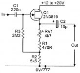
I found this schematic, would this be a good build for it?
That schematic shows a JFET, but it would "work". 2.2 Mohms and very little wiring capacitance would be reasonably favorable for the piezoelectric signal source. A MOSFET that could be used in that sort of topology is the DN2540N3-G.
FWIW, I was thinking bipolar PSU, to eliminate C1, along with (possibly) constant current sink (CCS) loading of the source follower.
If you use 100 Kohms for the 'X7 grid to ground resistance value, in the powered speaker control center, C2 in the FET cartridge buffer can be a 0.47 μF. film part. If at all possible, avoid electrolytic caps. in the "immediate" signal path. However, don't lose sight of the fact that the reservoir cap. of a PSU is in the signal path.
I was just goofing around with something like that (bipolar power supply for MOSFET source follower with gate at ground potential), but using a garden variety IRF5xx MOSFET you could probably find at your local electronics hobby shop.
The value of R4 adjusts how much drain current will run through the MOSFET.
I tried it in simulation with a resistor from source to -12VDC, but performance really suffers. THD increases by many orders of magnitude over the LM317 CCS. You could try a better CCS, but I'll bet the humble LM317 is good enough in this instance.
Would a JFET sound better than this MOSFET?
This should work with any JFET or even a plain old BJT, since the device will find its own source/emitter voltage with the gate held at ground potential by R1.
Just an idea. FWIW. I'm open to criticism.
--
PS - It looks like a ZVN0545A would work really well here.
--
Attachments

Last edited:
I like what rongon provided. 🙂
The 50 Kohm volume control would be eliminated in the arm pillar buffer application. The value of R1 becomes 10 Mohms, low noise metal film please. For the CCS, use a LR8. A 2 mA. drain current is plenty for this application and 2X TO-92 case devices per channel consume little space. FWIW, I'm thinking a +/- 24 VDC bipolar PSU exteral to, but nearby, the turntable. Occupy little space, within necessity's requirements, near the arm pillar's base.
The key parameter to good performance of any FET, in the source follower role, is low and stable reverse transfer capacitance (Crss). A substantial Crss causes HF info. loss. 😡 As the input impedance of MOSFETs is higher than that of JFETs, I prefer them here. In another situation, a JFET could easily be the best choice. Match the part to the requirements.
The 50 Kohm volume control would be eliminated in the arm pillar buffer application. The value of R1 becomes 10 Mohms, low noise metal film please. For the CCS, use a LR8. A 2 mA. drain current is plenty for this application and 2X TO-92 case devices per channel consume little space. FWIW, I'm thinking a +/- 24 VDC bipolar PSU exteral to, but nearby, the turntable. Occupy little space, within necessity's requirements, near the arm pillar's base.
Would a JFET sound better than this MOSFET?
The key parameter to good performance of any FET, in the source follower role, is low and stable reverse transfer capacitance (Crss). A substantial Crss causes HF info. loss. 😡
As the input impedance of MOSFETs is higher than that of JFETs, I prefer them here. In another situation, a JFET could easily be the best choice. Match the part to the requirements.If I used the schematic Rongon provided, 1 per channel, with your mod, at the tone arm could I then just run that through a simple 12AY7 preamp to drive the powered studio monitors (line in) directly and no longer need to attach an additional buffer on the output? 86 the 12SQ7s?
Last edited:
If I used the schematic Rongon provided, 1 per channel, with your mod, at the tone arm could I then just run that through a simple 12AY7 preamp to drive the powered studio monitors (line in) directly and no longer need to attach an additional buffer on the output? 86 the 12SQ7s?
Definitely keep the cathode followers. I question the ability of common cathode 12AY7 section to drive the powered monitors' I/P impedance. Unfortunately, the IHF "standard" 10 Kohm I/P impedance is lowest common denominator.
PS - It looks like a ZVN0545A would work really well here.
The ZVN0545A is a terrific part, but it's an enhancement mode device and will not self bias. 🙁 Use the ZVN0545A when it can be DC coupled to a thermionic device's plate. The requisite forward bias is a "no-brainer" under those conditions.
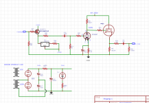
Ok, it looks like the probable build would look like this.
BTW, what is the likelihood I could build the dual rail power supply for the MOSFET circuit off the resistor under the voltage regulator tube?
BTW, what is the likelihood I could build the dual rail power supply for the MOSFET circuit off the resistor under the voltage regulator tube?
Attachments
Last edited:
- Home
- Amplifiers
- Tubes / Valves
- Pre-amp Buffer