When I tested/measured my KT88 CFB amp I had similar observation, triode mode = highest distortion. I've attached two KT88 OPS simulations, NonCFB (triode, ultra-linear, pentode) and CFB (triode, super-triode, super-pentode). The driver stage is an ideal voltage source, the distortion is simulated in two modes.
a / constant input voltage - V1, V2
b / constant output voltage - V(out)
Notice the bias current importance.


a / constant input voltage - V1, V2
b / constant output voltage - V(out)
Notice the bias current importance.
Attachments

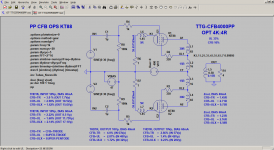
When I tested/measured my KT88 CFB amp I had similar observation, triode mode = highest distortion. I've attached two KT88 OPS simulations, NonCFB (triode, ultra-linear, pentode) and CFB (triode, super-triode, super-pentode). The driver stage is an ideal voltage source, the distortion is simulated in two modes.
a / constant input voltage - V1, V2
b / constant output voltage - V(out)
Notice the bias current importance.
Thanks for posting that. Do you have corresponding measurements, or just the simulation results?
I'm continuing my own investigations. I'm putting together a differential probe so I can accurately measure and account for the driver stage distortion in my measurements. I do not believe that the driver stage distortion has any impact on the relative distortion of the three modes (triode, UL, pentode) in my measurements, but it is thorough to check.
Having measured this effect with both the 7591A and EL34, and seeing your simulations with the KT88, I'm beginning to suspect it is a general rule.
Scott
LKA, can you post the distortion amplitude, phase for triode 10v 40ma , please. Use Ayumi model, much more precise in nonlinear . Latest Luxman , a re-edited circuit from 50's but with KT88 in triode , the spec says 0.5% Dtot at 1W. These distortions are mainly opposite phase odd order .
Having measured this effect with both the 7591A and EL34, and seeing your simulations with the KT88, I'm beginning to suspect it is a general rule.
Scott
I may be late to the party and missed a correction you need to check for. Your first schematic shows the EL-34 with an internal K-G3 connection that doesn't exist in that tube. You need an external pin 8-1 jumper. Have you discovered that yet? I skimmed through it all quickly and didn't see anything in that regard.
That intrinsic distortion of PP pentode stage, under certain conditions, is very low, is a fact well hidden in data sheets. One can compare, for example, 807 and 2A3 PP stages:
807 - 72W at <2%THD;
2A3 - 15W at 2.5% THD.
If 807 stage input is limited for 15W output, it's distortion will be less than 0.5%, or 5 times less than that of the 2A3 stage.
807 - 72W at <2%THD;
2A3 - 15W at 2.5% THD.
If 807 stage input is limited for 15W output, it's distortion will be less than 0.5%, or 5 times less than that of the 2A3 stage.
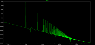
LKA, can you post the distortion amplitude, phase for triode 10v 40ma , please. Use Ayumi model, much more precise in nonlinear . Latest Luxman , a re-edited circuit from 50's but with KT88 in triode , the spec says 0.5% Dtot at 1W. These distortions are mainly opposite phase odd order .
KT88 PP Triode mode, 10Vp/4R/1k, bias 40mA
Harmonic Frequency Fourier Normalized Phase Normalized
Number [Hz] Component Component [degree] Phase [deg]
1 1.000e+03 9.573e+00 1.000e+00 -1.39 0.00
2 2.000e+03 8.461e-04 8.839e-05 -95.53 -94.13
3 3.000e+03 5.672e-01 5.925e-02 172.72 174.11
4 4.000e+03 1.464e-04 1.529e-05 -101.00 -99.61
5 5.000e+03 2.345e-02 2.450e-03 168.78 170.17
6 6.000e+03 1.480e-05 1.546e-06 -109.19 -107.80
7 7.000e+03 2.355e-04 2.460e-05 -70.48 -69.08
8 8.000e+03 1.561e-06 1.631e-07 -143.09 -141.69
9 9.000e+03 6.002e-04 6.269e-05 162.90 164.29
Total Harmonic Distortion: 5.929835%(5.929847%)
Attachments
Thanks for posting that. Do you have corresponding measurements, or just the simulation results?
Scott
I did measurements only for CFB OPS with global NFB.
EL34EH KT88EH behave similar and correspond simulation, KT77JJ is opposite.
TEST CONDITIONS: PP OPS, B+ 400V, Global NFB 10-15dB (OPS configuration and tube dependent)
BEST OPS CIRCUIT per TUBE (in terms of distortion, dummy load 4R5)
************************************************** ******
EL34EH, BIAS 40mA
-----------------------
1. CFB+UL (best)
2. CFB+ULX
3. CFB+TR
KT88EH, BIAS 60mA
-----------------------
1. CFB+ULX (best)
2. CFB+UL
3. CFB+TR
KT77JJ, BIAS 40mA
----------------------
1. CFB+TR (best)
2. CFB+UL
3. CFB+ULX
BEST OVERALL CIRCUIT and TUBE
***************************
THD 10W/4R5/1kHz
----------------------
1. KT77JJ CFB+TR - 0.06%
2. EL34EH CFB+UL - 0.1%
2. EL34EH CFB+ULX - 0.1%
2. KT88EH CFB+ULX - 0.1%
3. KT77JJ CFB+UL - 0.15%
THD 25W/4R5/1kHz
----------------------
1. KT88EH CFB+ULX - 0.13%
2. KT77JJ CFB+UL - 0.15%
3. EL34EH CFB+ULX - 0.22%
(no CFB+TR, 25W is a clipping region)
CFB+TR = CFB+TRIODE
CFB+UL = SUPER-TRIODE
CFB+ULX = SUPER-PENTODE
KT88 PP Triode mode, 10Vp/4R/1k, bias 40mA
Harmonic Frequency Fourier Normalized Phase Normalized
Number [Hz] Component Component [degree] Phase [deg]
1 1.000e+03 9.573e+00 1.000e+00 -1.39 0.00
2 2.000e+03 8.461e-04 8.839e-05 -95.53 -94.13
3 3.000e+03 5.672e-01 5.925e-02 172.72 174.11
4 4.000e+03 1.464e-04 1.529e-05 -101.00 -99.61
5 5.000e+03 2.345e-02 2.450e-03 168.78 170.17
6 6.000e+03 1.480e-05 1.546e-06 -109.19 -107.80
7 7.000e+03 2.355e-04 2.460e-05 -70.48 -69.08
8 8.000e+03 1.561e-06 1.631e-07 -143.09 -141.69
9 9.000e+03 6.002e-04 6.269e-05 162.90 164.29
Total Harmonic Distortion: 5.929835%(5.929847%)
I was right , The 3rd , 5th , and the 9th are of opposite phase. These distortions are going to subtract with ones you have in the DAC, preamp and specially the with those of the speaker. If you will be lacking DF ,apply negative voltage feedback about 6db and positive current one.
My intention in posting this data was not to create controversy. I was surprised and puzzled at the poor distortion performance of UL and triode modes (or alternately, I’m delighted at the superior performance of pentode mode). I’m still actively investigating and puzzling over this. Any other ideas?
Scott
Once again, is the EL34 (K-G3) jumper in place for these readings?
Once again, is the EL34 (K-G3) jumper in place for these readings?
Yes, the EL34 cathode and G3 are connected together on the circuit board. Sorry if that was unclear in the schematic.
Scott
Yes, the EL34 cathode and G3 are connected together on the circuit board. Sorry if that was unclear in the schematic.
Scott
OK. One other thing I'm curious about is your Zoebel network. It seems kind of aggressive with the 10R resistor. Have you tried getting specs without it in place? Or is your amp really that unstable that you need it?
OK. One other thing I'm curious about is your Zoebel network. It seems kind of aggressive with the 10R resistor. Have you tried getting specs without it in place? Or is your amp really that unstable that you need it?
The measurements were made without the Zoebel network components. I made provision for them on the PCB, but haven't used them yet. The amp is stable even with a 1uF capacitor across the 8 ohm load, using 17dB NFB.
I do plan to experiment with the Zoebel network components R73 and C1 in the future. I think they may have value if the amp is operated without a load.
C31 (labeled 10pF) was not used either. The unlabeled frequency compensation capacitor in the 6SL7 plate circuit was 82pF.
For measurements with NFB, Cfb was 1500pF. Rfb was varied to keep NFB at 17dB. The amp has fairly clean 10kHz square wave performance, I'll post some screen captures when I get a chance. I'm happy with the Triode A-470 output transformers. They have good performance over the 20Hz-20kHz range, and low distortion even at the band edges. Those transformers are better than a lot of pricey commercial products I've seen measured in Stereophile.
Scott
- Home
- Amplifiers
- Tubes / Valves
- PP EL34 Distortion: Triode > UL >> Pentode !?