Everything is stable. It's been on for over an hour and the heatsink has warmed up to a comfortable 35C
It's a pretty hopeless design as my speaker protection is almost continuously switching off the outputs.
I’m not sure if someone already said this but you should have one of the grounds on the board tied to the power supply ground for the front end reference.
My two cents,
My two cents,
I tired to help by providing a systematic approach to isolate your issue. Now these 14 posts of useless, erratic information. I am out of here.
I’m not sure if someone already said this but you should have one of the grounds on the board tied to the power supply ground for the front end reference.
My two cents,
All the GNDs are at the PSU star GND point.
I tired to help by providing a systematic approach to isolate your issue. Now these 14 posts of useless, erratic information. I am out of here.
I did as you said, bridging C1, that made absolutely no difference.
All the GNDs are at the PSU star GND point.
You sure? You seem to know what you're doing, but I don't see the GND for the boards. You have your input signal GND. You may have also done this after the photos - it is very difficult to keep track of what you've done.
Either way, with all you've gone through... it may be worth just giving it a look... see red circle. If you don't have something from one of the GND points to the PSU GND (or star GND) or some GND... it could be contributing to your issues.

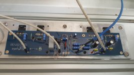
It seems from the above pic GND near the +/-IN is connected to the PSU ground instead of the RCA input ground. The ground from the PSU is not connected to either of the GND1, GND2. Try to remove the white cable to the GND near the +/-IN and connect to one of the grounds next to that. In place of the existing ground connection, take the ground of the RCA jack and connect.
There is also one other potential issue in that photo that I didn't call out b/c things were moving pretty quickly in the thread in the "early days" and many more experienced people were calling out some key things.
So.. Check your brown jumper too... It should run from signal GND to In-, I believe.
Again, I have no idea what's changed since that photo was taken. Just trying to help out. You've stuck with it. My suggestions may not currently be valid, if you've made changes.
Edited to add - I did not see manniraj's post. The In-, In+ and GND together are for the input signal to the best of my knowledge. I don't know where the white wire connects in his build, but in my builds - it connects to Pin 1 XLR => outside of RCA. Added new pic for clarity. Note, following my advice may not work... but it's how I built mine, and how I believe it is supposed to be done.

Good luck 🙂
So.. Check your brown jumper too... It should run from signal GND to In-, I believe.
Again, I have no idea what's changed since that photo was taken. Just trying to help out. You've stuck with it. My suggestions may not currently be valid, if you've made changes.
Edited to add - I did not see manniraj's post. The In-, In+ and GND together are for the input signal to the best of my knowledge. I don't know where the white wire connects in his build, but in my builds - it connects to Pin 1 XLR => outside of RCA. Added new pic for clarity. Note, following my advice may not work... but it's how I built mine, and how I believe it is supposed to be done.
Good luck 🙂
Last edited:
manniraj - 🙂
KatieandDad - I didn't read back through the whole thread. Giving you the benefit of the doubt - you may have put the shorting wire in place in that configuration just to set the offset and bias and intended to remove it and wire the inputs after.
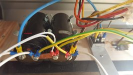
Rethinking this a bit - All 4 GND pads are on the same trace, I think - So, since I doubt you intended to use a 16AWG wire for your input... you likely ran that to your wire to the star GND... correct?
If that's what you've done...then you do have the GND reference for the amp board...
Hope you get it going. I've looked it over and over and don't see anything new 🙂
KatieandDad - I didn't read back through the whole thread. Giving you the benefit of the doubt - you may have put the shorting wire in place in that configuration just to set the offset and bias and intended to remove it and wire the inputs after.
Rethinking this a bit - All 4 GND pads are on the same trace, I think - So, since I doubt you intended to use a 16AWG wire for your input... you likely ran that to your wire to the star GND... correct?
If that's what you've done...then you do have the GND reference for the amp board...
Hope you get it going. I've looked it over and over and don't see anything new 🙂
There is also one other potential issue in that photo that I didn't call out b/c things were moving pretty quickly in the thread in the "early days" and many more experienced people were calling out some key things.
So.. Check your brown jumper too... It should run from signal GND to In-, I believe.
Again, I have no idea what's changed since that photo was taken. Just trying to help out. You've stuck with it. My suggestions may not currently be valid, if you've made changes.
Edited to add - I did not see manniraj's post. The In-, In+ and GND together are for the input signal to the best of my knowledge. I don't know where the white wire connects in his build, but in my builds - it connects to Pin 1 XLR => outside of RCA. Added new pic for clarity. Note, following my advice may not work... but it's how I built mine, and how I believe it is supposed to be done.
View attachment 845544
Good luck 🙂
Yes, I've now got +in -in and GND connected together. I've still got the same problem.
manniraj - 🙂
KatieandDad - I didn't read back through the whole thread. Giving you the benefit of the doubt - you may have put the shorting wire in place in that configuration just to set the offset and bias and intended to remove it and wire the inputs after.
Rethinking this a bit - All 4 GND pads are on the same trace, I think - So, since I doubt you intended to use a 16AWG wire for your input... you likely ran that to your wire to the star GND... correct?
If that's what you've done...then you do have the GND reference for the amp board...
Hope you get it going. I've looked it over and over and don't see anything new 🙂
I'm using 2.5mm cable throughout. I'm sure it's not a ground loop problem.
There are only 4 wires connected to the J. +ve, -ve, GND and SPKR OUT, all with 2.5mm cable. All GND references are to the 0V star point between the two filter caps, 33000uF each.
Attachments

Last edited:
This may be the worst advice ever... I can't remember if you've stuffed the the other board... If so...
If you haven't already, I'd personally make all the known corrections to get it per the schematic (bias and offset jumpers etc.) that you did on this board and fire it up. As I recall, you've been through the board with a fine-toothed comb. Comparing measurements could help you and others narrow it.
If it behaves precisely the same way... then that's also valuable information.
Again, it's not what I'd do with my "day job". It's poor QA practice... and there is a bit of risk.. but... what have you got to lose?
- Home
- Amplifiers
- Pass Labs
- Aleph J Setting DC Offset