Hello everyone!
I'm trying to get back into the swing of things in the tube world. When I was a teenager, I got interested in tubes and DIY audio in general, built a little tube preamplifier kit, and then promptly got hit with the real world when I moved out of my parents house and enlisted the USMC. Been a free man again for a while now, finished my degree, and got a real job, so now I want to get back into the DIY audio world. My hearing actually super damaged from crewing on the CH53E, but I've always wanted to design and build a tube amp; just copying someone else schematic won't itch the spot.
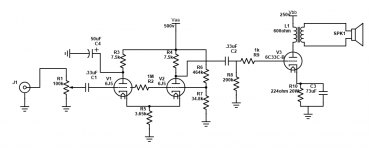
Been spending my time reading "Valve Amplifers" - 3rd edition (bought it when I was a teenager), and playing around with TubeCAD and SE Amp CAD, on a WinXP virtual box, as well as reading whatever I can find online. The following circuit is what I've come up with: Imgur: The magic of the Internet
The outputs from TubeCAD and SE Amp CAD: Imgur: The magic of the Internet
Some notes -
Any glaring flaws that will make it blow up in my face at power on?
My goal is to get the circuit as good as possible before I buy parts to build a single channel to play around with.
Also, I'm a Forester for the USFS nowadays, ask me a tree related question!
I'm trying to get back into the swing of things in the tube world. When I was a teenager, I got interested in tubes and DIY audio in general, built a little tube preamplifier kit, and then promptly got hit with the real world when I moved out of my parents house and enlisted the USMC. Been a free man again for a while now, finished my degree, and got a real job, so now I want to get back into the DIY audio world. My hearing actually super damaged from crewing on the CH53E, but I've always wanted to design and build a tube amp; just copying someone else schematic won't itch the spot.
Been spending my time reading "Valve Amplifers" - 3rd edition (bought it when I was a teenager), and playing around with TubeCAD and SE Amp CAD, on a WinXP virtual box, as well as reading whatever I can find online. The following circuit is what I've come up with: Imgur: The magic of the Internet
The outputs from TubeCAD and SE Amp CAD: Imgur: The magic of the Internet
Some notes -
- 6C33C-B (yes I know the cyrillic is actually different letters, before someone points that out), was chosen as the output tube simply because I really like the way they look.
- 6J5 was chosen as the driver because, again, I like the look of the metal tubes, and I think, from what I seen in TubeCAD, they will have no issues driving the 6C33C-B
- The 6J5 grids are tied together with a 1 mega ohm resistor
- OPT is TTG-6C33CS
- SE Amp CAD says this isn't going to be a low distortion amp, but I'm going in knowing this. If it is really bad, maybe I can add some negative feedback? - My hearing probably isn't good enough anymore to actually tell.
- Intended speaker will be Fostex full range drivers (not sure which ones yet)
Any glaring flaws that will make it blow up in my face at power on?
My goal is to get the circuit as good as possible before I buy parts to build a single channel to play around with.
Also, I'm a Forester for the USFS nowadays, ask me a tree related question!
First off.... your schematic will be silent....
look where the cap is on the plate of the first triode. Building tube gear is a process, not a one time shot.
Copying some else who knows what they are doing is NOT a bad thing....
also, the 1 meg on the grid of the 2nd triode is way too much, 1k would do...
just friendly advice 🙂
look where the cap is on the plate of the first triode. Building tube gear is a process, not a one time shot.
Copying some else who knows what they are doing is NOT a bad thing....
also, the 1 meg on the grid of the 2nd triode is way too much, 1k would do...
just friendly advice 🙂
@mctavish:
The schematic might be silent - in fact they are most of the time - however the circuit when built as drawn will not.
I think you completely missed the functionality:
The left triode works as a cathode follower, hence cap filtered power supply on its plate.
The right triode works as a grounded grid amplifier for the signal developed across the shared cathode resistor by said cathode follower.
Both grids are biased from a common resistor divider, left thru 1M, the right one directly.
I did not calculate the numbers but if the divider is set correctly it will work.
Nothing is missing, nothing is unnecessarily shared, nothing seriously wrong, imho.
Attachments
Last edited:
The 2nd harmonic of the dual triode stage is partially canceled by the topology.
That is why the circuit looks strange.
That is why the circuit looks strange.
look where the cap is on the plate of the first triode. Building tube gear is a process, not a one time shot.
It probably wont be a one time shot, but I also have to be realistic about the hobby too. I thought about giving a go at building a 829B schematic I've seen, but ultimately I know I can successfully follow a schematic though. So I don't really want to spend the $$$ on a project, that I know I can do, and also know I won't really use.
IDK, I am not always great at conveying what I really mean. I probably am not using the right words there. Just know I'm not trying to be negative, I do understand what you are saying.
Sorento hit the nail on the head about the common cathode. I am actually unsure at how big the capacitor coming off of the first plate should be. TubeCAD doesn't spit out a value, and a TubeCAD article about common cathode amplifiers, just said it should be large valued. I've seen a similar schematic where 47uF was used, so I just rounded up there. I'm figuring that may be a point where I try some different values to see what works best. As far as the voltage divider that feeds back into both grids, I'm also thinking about using pots, so I can fine tune it.
Definitely going to stay positive. Next part is rolling up an appropriate power supply from off the shelf parts.
- Home
- Amplifiers
- Tubes / Valves
- TubeCAD to real life *newbie*