I'm a voltage regulator man, as in comparing the regulator output to some reference and adjusting the output to the wanted value.
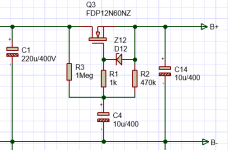
But sometimes you see designs that use a capacitance multiplier instead, which basically is an open loop emitter or source follower, as in the attached schematic fragment.
What is not clear to me is how this works under varying load. I guess that the gate voltage is slowly coming up when C4 charges, but to what level?
Also, if I suddenly draw a larger current, the output voltage must drop because the gate voltage stays what it is.
Anybody can offer some clarification here?
Jan
Attachments
Vin - Vout = (Vgs/R2)(R2+R3) ?What is not clear to me is how this works under varying load. I guess that the gate voltage is slowly coming up when C4 charges, but to what level?
Let's give it a try.Also, if I suddenly draw a larger current, the output voltage must drop because the gate voltage stays what it is.
Larger current, small Vout drop to give more Vgs needed.
If Vin try to dorp below Vout, Vout goes down too making Vgs greater (if not to long for C4).
The fet conducts more and Vin = ~Vout with the ripple.
A larger current that lasts (with lower Vin) make C4 settle on a lower voltage and all goes well as long as the ripple stay well above Vout.
Mona
Attachments
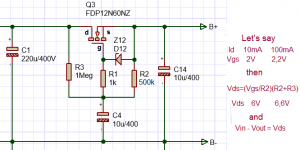
Well, choose R2 and R3 to have enough voltage across the fet.How do you make sure that Vout stays below the minimum ripple?
Jan
Mona
OK so in the shown circuit, Vds is about 3 x Vgs.
With Vgs a nominal 2.5V, that means it can handle ripple voltages of 7.5V peak.
That then needs to be corrected because Vg (to gnd) is ~approx[ Vin (peak)] - [0.5 x Vripple(peak)].
Probably easier to sim ;-)
Jan
With Vgs a nominal 2.5V, that means it can handle ripple voltages of 7.5V peak.
That then needs to be corrected because Vg (to gnd) is ~approx[ Vin (peak)] - [0.5 x Vripple(peak)].
Probably easier to sim ;-)
Jan
C4 has a mean value, ½Vripple(peak) goes only if the ripple is symetrical. Often short up and longer dawn.But the up-side doesn't hurt so with ½ I supose you are on the safe side.OK so in the shown circuit, Vds is about 3 x Vgs.
With Vgs a nominal 2.5V, that means it can handle ripple voltages of 7.5V peak.
That then needs to be corrected because Vg (to gnd) is ~approx[ Vin (peak)] - [0.5 x Vripple(peak)].
Probably easier to sim ;-)
Jan
Mona
You can extract a voltage equal to VINmin, i.e., the trough of the input ripples.
You can set VOUT = VINmin - K volts, for some constant K that pleases you.
This has the advantage of tracking the AC mains voltage, so you don't have to build in a worst case mains-droop assumption at all times. When the mains droops, the output sags ... BUT when the mains doesn't droop, the output rises.
Yes, clear.
The elephant in the room though is the leakage current of C4. A mainstream 10uF/400V electrolytic is specified at 440uA leakage max. Through the 1Meg resistor, that's a huge drop. Arguably, that 440uA is a max at elevated temperatures, but still.
I noticed that no two nominally identical cap multipliers gave the same output, some 20V below Vin, some 40V, some 5V. Apparently it is the difference in C4 leakage current.
You guys have experienced something like that? How to cope with that?
Jan
No experience with mosfet's nor simulation.I'm very oldYou guys have experienced something like that? How to cope with that?
 , studied electronic at the NaRaFi back in the early '60.
But I would say, don't use an electrolytic for C4.
Mona
That's Jack Bybee's MusicRail circuit
Home
https://patentimages.storage.googleapis.com/ef/19/a0/83d9c4c7d42b19/US7521990.pdf
R2 seems to have no function except to accelerate startup, and damage PSRR. A diode would help.
Home
https://patentimages.storage.googleapis.com/ef/19/a0/83d9c4c7d42b19/US7521990.pdf
R2 seems to have no function except to accelerate startup, and damage PSRR. A diode would help.
That C isn't that big 😉Do you know how large a 10uF/400V film cap is?? If you can get it.
About the size of a can of Jupiler. ;-)
BTW, what is the function of R2 in the attached circuit?
Jan
As for R2, it represents a high load to Vin at high frequencies and no load at DC like a capacitor. To do what ??
Mona
Attachments

The voltage drop depends on Rout, which is 1/gm. Gm depends on the drain current in the FETWhat is not clear to me is how this works under varying load. I guess that the gate voltage is slowly coming up when C4 charges, but to what level?
Also, if I suddenly draw a larger current, the output voltage must drop because the gate voltage stays what it is.
Anybody can offer some clarification here?
Jan
Crude method: dimension the resistors to always remain within the limit.How do you make sure that Vout stays below the minimum ripple?
Jan
Or use a clever scheme: for example with a diode anti-peak detector to track the troughs.
A time constant of 10s is utterly insane: with an open-loop reg or cap-mult, the PSRR is limited by the Early effect or the lambda parameter.Yes, clear.
The elephant in the room though is the leakage current of C4. A mainstream 10uF/400V electrolytic is specified at 440uA leakage max. Through the 1Meg resistor, that's a huge drop. Arguably, that 440uA is a max at elevated temperatures, but still.
I noticed that no two nominally identical cap multipliers gave the same output, some 20V below Vin, some 40V, some 5V. Apparently it is the difference in C4 leakage current.
You guys have experienced something like that? How to cope with that?
Jan
For both bjt and FETs, it sets the ultimate rejection to ~60dB, give or take 10dB (depends on the exact device)
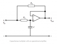
I guess the novelty, if any, is the application for AC with the boost transformer. The circuit I posted is a well-known capacitance multiplier when looked at from the opamp output pin. Send a current into that output and it looks like a low pass with 10^4 times the 100pF.
In that circuit, the Bode plot shows -3dB at 1Hz. With a 100pF cap ...
Jan
In that circuit, the Bode plot shows -3dB at 1Hz. With a 100pF cap ...
Jan
Last edited:
[snipped good points]
A time constant of 10s is utterly insane: with an open-loop reg or cap-mult, the PSRR is limited by the Early effect or the lambda parameter.
For both bjt and FETs, it sets the ultimate rejection to ~60dB, give or take 10dB (depends on the exact device)
Agreed. If you make the series R 100k, you still have 1s RC and the leakage current from the cap has 1/10th the impact.
Jan
- Home
- Amplifiers
- Power Supplies
- The lowdown on cap multipliers