Hello,
I wasn't sure where to ask this question, but since I'm working with a tube amp, I'm asking here.
OK, I have drawn (copied) an SET tube amp schematic in LTSpice.
Now, I would like to run a simulation so that I can measure DC voltages at the tubes, specifically the voltages at the cathode, plate, and screen grid.
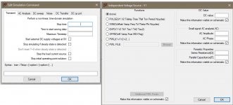
I have absolutely no idea what to enter into the fields in the screenshots I've attached.
Thanks for help with this. I have spent many hours Googling, reading how-to's and watching videos, but I cannot find any examples to copy.
I wasn't sure where to ask this question, but since I'm working with a tube amp, I'm asking here.
OK, I have drawn (copied) an SET tube amp schematic in LTSpice.
Now, I would like to run a simulation so that I can measure DC voltages at the tubes, specifically the voltages at the cathode, plate, and screen grid.
I have absolutely no idea what to enter into the fields in the screenshots I've attached.
Thanks for help with this. I have spent many hours Googling, reading how-to's and watching videos, but I cannot find any examples to copy.
Attachments
Thanks Mooly.
The problem I'm having is that I have two voltage sources:
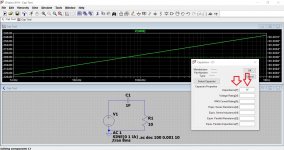
1) I have 120V AC attached to my power transformer. I think this is supposed to be 169.7V, but I don't know how to enter that information into Spice.
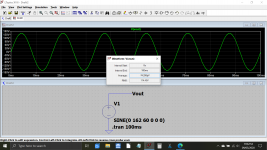
2) I need an AC signal input. In my case that's a 1/4" jack connecting to the grid of the preamp tube (imagine the pickup of an electric guitar plugged into the amp).
I followed your guide, but what I can't figure out - or, understand - is how to simulate 120V AC connected to my power transformer, and how to simulate an AC signal feeding into the first tube's grid.
I will keep searching and reading. I know that others have simulated this same scenario that I'm trying to run.
The problem I'm having is that I have two voltage sources:
1) I have 120V AC attached to my power transformer. I think this is supposed to be 169.7V, but I don't know how to enter that information into Spice.
2) I need an AC signal input. In my case that's a 1/4" jack connecting to the grid of the preamp tube (imagine the pickup of an electric guitar plugged into the amp).
I followed your guide, but what I can't figure out - or, understand - is how to simulate 120V AC connected to my power transformer, and how to simulate an AC signal feeding into the first tube's grid.
I will keep searching and reading. I know that others have simulated this same scenario that I'm trying to run.

Hello,
I wasn't sure where to ask this question, but since I'm working with a tube amp, I'm asking here.
OK, I have drawn (copied) an SET tube amp schematic in LTSpice.
Now, I would like to run a simulation so that I can measure DC voltages at the tubes, specifically the voltages at the cathode, plate, and screen grid.
I have absolutely no idea what to enter into the fields in the screenshots I've attached.
Thanks for help with this. I have spent many hours Googling, reading how-to's and watching videos, but I cannot find any examples to copy.
In the attached file there is a short "how to" of LTspice.
For your question you can immediately go to page 7 and start working on those examples there.
For me this was a great start and in my humble opinion your questions are answered there.
Attachments
Thanks Joe! I will read that.
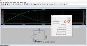
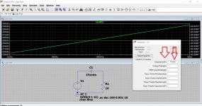
However, a member on another forum fixed the problem I was having by pointing out that in LTSpice 1M is NOT a megaohm, but a milliohm! I changed one resistor value from 1M to 1Meg and my measurements fell into place.
However, a member on another forum fixed the problem I was having by pointing out that in LTSpice 1M is NOT a megaohm, but a milliohm! I changed one resistor value from 1M to 1Meg and my measurements fell into place.
I've been caught out with units in LT and it took me a while to figure out. If you miss the multiplier (such as uF or Meg etc) out then don't assume LT uses what should be (to me) the base units for that part which confusing is shown in the window you enter the value into. For example:
1 = 1ohm
1 = 1 Henry
both as expected, however 1 for a cap isn't 1 Farad but 1 Femto Farad. Weird but that is the way it is. You have to enter 1F if that is what you want.
1 = 1ohm
1 = 1 Henry
both as expected, however 1 for a cap isn't 1 Farad but 1 Femto Farad. Weird but that is the way it is. You have to enter 1F if that is what you want.
I've got it back to front by the looks of it. Confusing because the F (for Farad) is clearly shown as what is assumed to be the base unit. For Ohms and Henry it is and yet 1F is apparently 1 Femto. The last two images simulate the same.
Attachments
- Home
- Amplifiers
- Tubes / Valves
- LTSpice simulation settings.