I'm just looking for a little advice here.
I've built a stereo 3-way active crossover following the Elliott Sound Design schematic and using a pair of Salas SSLV 1.3s to provide the +/- 15v for the boards however I'm facing a -3v surge on power off as the op-amp voltage drops.
My thoughts are to use a few relays to switch the output off on power loss, but I was also thinking perhaps there's a way to even the voltage drop so the op-amps (LM4562) behave 'properly'.
Thoughts?
From elliot sounds project 09.
As noted above, some opamps create a transient signal upon application or removal of power. Because this they will create a loud sound, many builders may want to incorporate a delayed action switch, to ensure that the outputs of the circuit are not connected to the load until the operating conditions have stabilised. One simple solution is described above, and will work perfectly. Alternatively, the P05 Rev-B power supply has an auxiliary output that is designed to be used for muting. The TL072 is one of the worst for this problem, and it is usually not a problem with NE5532 or OPA2134 opamps.
Although the transients are unlikely to cause damage to any amplifier or loudspeaker, they do not sound very nice. For a system that you build yourself, there is a great satisfaction in having it perform flawlessly, so it is probably worth the small effort to use the P05-C supply's aux output to drive muting relays.
From elliot sounds project 09.
As noted above, some opamps create a transient signal upon application or removal of power. Because this they will create a loud sound, many builders may want to incorporate a delayed action switch, to ensure that the outputs of the circuit are not connected to the load until the operating conditions have stabilised. One simple solution is described above, and will work perfectly. Alternatively, the P05 Rev-B power supply has an auxiliary output that is designed to be used for muting. The TL072 is one of the worst for this problem, and it is usually not a problem with NE5532 or OPA2134 opamps.
Although the transients are unlikely to cause damage to any amplifier or loudspeaker, they do not sound very nice. For a system that you build yourself, there is a great satisfaction in having it perform flawlessly, so it is probably worth the small effort to use the P05-C supply's aux output to drive muting relays.
Thanks for that, I have read that and have considered going down this route but was also looking at other options.
For example, I've just parallelised an additional 4700uf cap on the existing 10000uf to give the positive line a little more and the -3v is now a max of +1v on power off.
I'm building the exact same filter, but waiting for tulip sockets and opa2134, your finding with adding more capacitance sounds promising, and might be a fix, if not the relay pulling to ground will surely work.
I will probably also be facing same issue, what opamps are you using?
I will probably also be facing same issue, what opamps are you using?
Attachments

I'm building the exact same filter, but waiting for tulip sockets and opa2134, your finding with adding more capacitance sounds promising, and might be a fix, if not the relay pulling to ground will surely work.
I will probably also be facing same issue, what opamps are you using?
Yes, exactly the same filter.
I'm using LM4562 and LME49720 (the basically same opamp) I've got plenty of 5532s and a few OPA2134s and could look at replacing all on one board to see if the negative spike is still there.
Alternatively I'll probably look at wiring in a 240 to 12v LED PSU and using this to control a relay, would the relay on the +/- power lines to the boards work or would I need to place the relays on the lo/med/hi outputs just to be sure?
and using a pair of Salas SSLV 1.3s to provide the +/- 15v for the boards however I'm facing a -3v surge on power off as the op-amp voltage drops.
You have scaled down the filter caps to a sensible value for the current draw? For small signal stuff having more filter capacitance than needed will only increase the transient duration with no benefit.
You have reverse-protection diodes between each rail and ground? These prevent one rail pulling the other across ground (one of the few ways to trash opamps). Without them transients may be worse.
You have scaled down the filter caps to a sensible value for the current draw? For small signal stuff having more filter capacitance than needed will only increase the transient duration with no benefit.
Good point Mark, perhaps 10000uf is a little too large for the job at hand.
You have reverse-protection diodes between each rail and ground? These prevent one rail pulling the other across ground (one of the few ways to trash opamps). Without them transients may be worse.
Hmmm, that's an easy one to test, let me have a play.
Thanks Mark, really appreciate your advice.
I've made a 3-way active box with a similar problem at switching on and off.
the poweramps I used are TDA7264, very simple.
I modified the mute-circuit in such a way that the amp only sounds after the voltages are stable and stops before the power supply is already gone.
the poweramps I used are TDA7264, very simple.
I modified the mute-circuit in such a way that the amp only sounds after the voltages are stable and stops before the power supply is already gone.
You have reverse-protection diodes between each rail and ground? These prevent one rail pulling the other across ground (one of the few ways to trash opamps). Without them transients may be worse.
That didn't help I'm afraid, I placed a couple of Schottkys on the rails and still had the -ve surge through the low/medium/high outputs.
I'll probably look at using a few 12v relays connected to each of the outputs.
A shame it didn't work, did you try the ne5532 ?
Take a look on sound-au.com project 144 mains power sequenser, I am considering it to turn on/off amps and crossover in a predetermined order, to avoid speaker thump, also considering mosfet relays to protect the tweeters that are in danger now that it's capacitor is gone.
Take a look on sound-au.com project 144 mains power sequenser, I am considering it to turn on/off amps and crossover in a predetermined order, to avoid speaker thump, also considering mosfet relays to protect the tweeters that are in danger now that it's capacitor is gone.
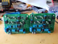
Here's mine, please excuse the rough layout, I'm still playing with the layout and the wiring.
I've used PRP metal film resistors and Wima PP caps, I had to be a little creative with the Wimas as they are little too large for the board so they are mounted on the underneath. Also I put some bypass caps on the op-amp power lines.
I did try using some 5532s but the same issue occurred.
I've used PRP metal film resistors and Wima PP caps, I had to be a little creative with the Wimas as they are little too large for the board so they are mounted on the underneath. Also I put some bypass caps on the op-amp power lines.
I did try using some 5532s but the same issue occurred.
Attachments
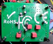
You picked the red theme, I the blue🙂 I read the papers on the opa2134 and it suggested 10nf ceramic decoupling as close as possible to pins, I see you use much more, could that have a negative effect regarding surge?
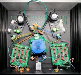
I would divide that chassis internally with aluminium sheet and place trafo and regs separately.
You picked the red theme, I the blue🙂 I read the papers on the opa2134 and it suggested 10nf ceramic decoupling as close as possible to pins, I see you use much more, could that have a negative effect regarding surge?
I'm using a 0.1uf and 10uf in parallel as I've used on other op-amps requirements (IV buffers on DACs) I didn't have any ceramics to hand so used a film.
Did you drill through pcb and catch gnd?
No, I'm safe there, I was pretty careful.
I would divide that chassis internally with aluminium sheet and place trafo and regs separately.
My thoughts too, I'd even considered building a metal mesh shield over the boards.
How are you powering your boards? I've got a couple of other options but really wanted to use a pair of these SSLVs from the group buy on here.
Mine are just powered by lm317 37, not the most low noise but with careful filtering it should be okay, but as you I've been looking for some superregs, maybe Jan diddens.
I'm curious what is the setup what amps will they power and what speakers?
Yes some sort of shielding of the ac part would be a good idea, also keeping in/out cabeling as short as doable, I've seen some who put in a second aluminium sheet as bottom of amplifier chassis, raised it so its has 10 to 20mm gab, and then had all wiring underneath
Mine are just powered by lm317 37, not the most low noise but with careful filtering it should be okay, but as you I've been looking for some superregs, maybe Jan diddens.
I'm curious what is the setup what amps will they power and what speakers?
Yes some sort of shielding of the ac part would be a good idea, also keeping in/out cabeling as short as doable, I've seen some who put in a second aluminium sheet as bottom of amplifier chassis, raised it so its has 10 to 20mm gab, and then had all wiring underneath
I've got an Audiowind LM317/337 board that I used initially which didn't have the issue and a low-noise Zero Zone POWER-02 which did, both of these are significantly smaller than the Salas boards however!
I've got a pair of Marantz MA22 power amps for the mid and two Linn AV5105 (LK240) providing the low and the high, I've been running a pair of miniDSP 2x4HD for three years so know exactly the 'correct' crossover frequencies and gain differences. I've converted, well removed the crossovers from my Heybrook Sextets to support this config.
It's the cabling that's troubling me, I don't want to introduce another circuit off the +ve rail to deal with a relay switching, hence thinking about using a simple LED lighting PSU but then I'll be soldering in 6 relays and the wiring for those, it starts to get very messy and sort of ruins my idea of purity.
I'm really glad there's the two of us using these boards, great to share views!
Update: I have been misreading my digital multimeter, it wasn't until I videoed the power-off and replayed the video back slowly that I noticed it was swinging from -390mV to 300mV, I got caught out with the jump from positive to negative and assumed a magnitude higher.
I think this might be manageable, time to play with a cheap speaker!
I think this might be manageable, time to play with a cheap speaker!
That's a nice setup you got there, I have one channel playing, just loosely, jlh class a for tweeter, and the simple killer amp from greg ball for mids, bass is run by a bryston 4bsst home brew, speakers are also home brew, 3 way JBL, 15/10/1 inch
Sound is very clear, but theres some level adjustment to do, gain varies between amps.
What crossover points did you use?
Sound is very clear, but theres some level adjustment to do, gain varies between amps.
What crossover points did you use?
- Home
- Source & Line
- Analog Line Level
- 3-way active crossover, opamp instability on power loss