Hello! I have a Musical Fidelity V2 DAC and trying to understand the power supply plan.
It uses unipolar power supply 12V and for the opamps creates the negative rail using two DCDC charge pumps LMC7660 from TI.
When measuring the two rails that feeds opmaps i measure a difference of minimum 1.5V and i want to try and correct this issue if possible.
As can be seen on the picture the positve rail goes almost unchanged from power supply to opamps.
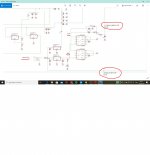
The input on pin 8 of charge pumps is 8,9V and on pin 5 I measure 7,8V. I was expecting to have Vout equal -Vinput.
The group formed by C21,C44, D3, D4 also confuses me because in the end I have -12,6V on opamp negative rail.
What is the role of C21,C44, D3, D4?
What can I do to have equal voltages on opamps rails?
I attached the complete schematic of DAc and also a screenshot with measured voltages.
Thanks! Adrian
It uses unipolar power supply 12V and for the opamps creates the negative rail using two DCDC charge pumps LMC7660 from TI.
When measuring the two rails that feeds opmaps i measure a difference of minimum 1.5V and i want to try and correct this issue if possible.
As can be seen on the picture the positve rail goes almost unchanged from power supply to opamps.
The input on pin 8 of charge pumps is 8,9V and on pin 5 I measure 7,8V. I was expecting to have Vout equal -Vinput.
The group formed by C21,C44, D3, D4 also confuses me because in the end I have -12,6V on opamp negative rail.
What is the role of C21,C44, D3, D4?
What can I do to have equal voltages on opamps rails?
I attached the complete schematic of DAc and also a screenshot with measured voltages.
Thanks! Adrian
Attachments
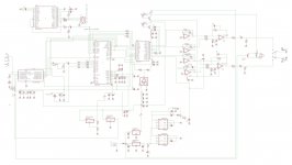
I think this is the V1 schematic because there is relay K1 on the output. V2 has mute transistors. I am not aware of other differences.
The analogue stage rails voltages are indeed assymetric (10.3V/-12.78V) but I believe it was done on purpose, so no need to correct that, unless you want to feed the op amps with external voltages and disconnect IC2 and IC7.
Two charge pumps are connected in parallel and the C44/D4 and the opposite-polarized C21/D3 are there to attenuate fluctuations between them.
Quality of PCB and of soldering on this MF is bad. After one year of using it, I got a hum on one channel, which was caused by a cracked joint in an area of PCB I didn't even work on. You can remove caps by carefully wiggling them along the axis connecting two pads, while pressing downwards - they will pop out without lifting pads.
Two charge pumps are connected in parallel and the C44/D4 and the opposite-polarized C21/D3 are there to attenuate fluctuations between them.
I agree, the two charge pumps are connected in parallel (both pin 5 are united) but the C44/D4 and C21/D3 groups are connected after that in a strange way for me. I measured on input of this group 7.8V and after it i measure 12.6V.