Hi Diyaudio,
While staying at home for COVID reasons, I'm studying different 45/2A3 DC coupled schematics. the following schematic from Shishido San is puzzling me.
What could be the purpose of 22k resistor, between the 300 V B+ supply of the first stage, and the cathode resistor of the power triode ?
Thanks for your assistance. Warm regards,
Jerome
Attachments
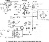
That´s a direct coupled amplifier.
He has "way too much" (for the power tube) voltage at the driving tube plate (150V), but he needs -45V grid to cathode at the power tube, so he needs to rise cathode voltage to meet that.
150V-195V=-45V
He has "way too much" (for the power tube) voltage at the driving tube plate (150V), but he needs -45V grid to cathode at the power tube, so he needs to rise cathode voltage to meet that.
150V-195V=-45V
Pretend that you power on the amplifier without the 12AX7. What happens with that resistor, and what happens without it?
Although this seems unreasonable, it's totally possible for the 12AX7 to fail in general, and that resistor is offering some protection from that.
Although this seems unreasonable, it's totally possible for the 12AX7 to fail in general, and that resistor is offering some protection from that.

Member
Joined 2009
Paid Member
One explanation that is sometimes giving is that this is a B+ bleeder resistor for the supply of the first triode, it maintains a current flow through the RC filter on the power rail and lessens the variation in current from the signal current flowing through the first triode
as for failure of the first triode, the main protector of the output tube is the cathode resistor which you will notice rather large - when you consider how much current can flow through the output tube Regardless of the voltage on the grid you will see it is fairly safe
as for failure of the first triode, the main protector of the output tube is the cathode resistor which you will notice rather large - when you consider how much current can flow through the output tube Regardless of the voltage on the grid you will see it is fairly safe
as for failure of the first triode, the main protector of the output tube is the cathode resistor which you will notice rather large - when you consider how much current can flow through the output tube Regardless of the voltage on the grid you will see it is fairly safe
So, the 12AX7 failing without the 22K resistor will make the 2A3 into a diode, and it will do its best to conduct the full 150mA that it can across the 3K cathode bias resistor.
The voltage across that resistor will rise, and either the bypass cap will blow and fail short (which will then defeat the "safety" of the 3K resistor), or the 3K resistor will overheat and open up, then that cap will blow anyway. The 2A3 isn't likely to survive this ordeal.
With the 22K resistor there, an open 12AX7 causes the bias voltage to increase to 100V P-K, which dramatically decreases the current drawn by the 2A3.
Also note that the 12AX7 is far slower to warm up than a 2A3, so when the amp is turned on and the 2A3 is ready to rock, this resistor limits its current draw quite nicely.
Member
Joined 2009
Paid Member
I’m not suggesting that the resistor to have no benefit but that the circuit can survive without.
After taking the grid of the 2a3 positive we’ll see an increased voltage drop in the rectifier, across the power supply choke and the output transformer so that only 400V remain. The cathode resistor along with the internal resistance of the tube will limit the current to just over 100mA and the large voltage drop across the cathode resistor will limit the plate dissipation.
The biggest current spike occurs at power up when the cathode experiences the low impedance to ground of the cathode bypass capacitor. Only the warm up of the rectifier provides comfort.
fyi - other authors have argued that the first tube need not be paralleled; I refer to Dennis Fraker and Jeff Medwin.
Last edited:
After taking the grid of the 2a3 positive we’ll see an increased voltage drop in the rectifier, across the power supply choke and the output transformer so that only 400V remain. The cathode resister along with the internal resistance of the tube will limit the current to just over 100mA and the large voltage drop across the cathode resistor will limit the plate dissipation.
This is still enough to damage the 250V cathode bypass cap, as well as too much dissipation for the 3K cathode bias resistor. One of the two (or both) will still pop and make a mess of trouble.
Member
Joined 2009
Paid Member
I do not suggest leaving off the 22k resistor but I would suggest seasoned constructors usually ensure that the Cathode resistor be sized with the usual de-rating design margin. Capacitor choice is a larger topic, including consideration of the ‘Western Electric’ cap from cathode to B+ for hum reduction if not implementing the true L-W hum reduction topology for which I refer you here: Loftin White: PC86 RL12T15 Darius Loftin White
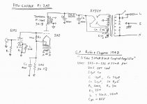
Another version you might like is attached, by Robin and Chapman in 1947 and made famous by Don Garber in his very well regarded Fi amplifier.
Another version you might like is attached, by Robin and Chapman in 1947 and made famous by Don Garber in his very well regarded Fi amplifier.
Attachments
Last edited:
The 2A3 filament heats up almost instantly.
The 12AX7 cathode heats up very slowly.
That means without the 22k resistor, the 2A3 conducts lots of current, unless the 12AX7 warms up before the 5AR4 warms up.
Are you testing the warm up time of your 12AX7 versus the warm up time of your 5AR4?
If not, then keep the 22k resistor in there.
Also, taking the 22k out will disturb the DC levels even when the tubes are warm.
Then you will have to change the 25k resistor to restore the DC level.
And then someone always wants to replace the 5AR4 with a solid state rectifier substitute.
Even if that substitute has a series resistor to drop the B+ to the same voltage as with the 5AR4.
But the almost instant on B+ when using a solid state rectifier, will cause the very large 2A3 current, until the 12AX7 warms up.
All the above problems will happen, even if the 12AX7 never dies.
Do not take out the 22k resistor.
Last edited:
Hello Gents,
First I'd like to thanks very much all of you for your contributions.
As all of you state, the indirectly heated input valve will require several tens second to warm up and bias, when the DHT valve needs only seconds to power up and conduct.
With the 22 k resistor during power up, 2.5 seconds later B+ has establish (450 V) (time constant made by 25 k & 100 µ), we'll have 325 V of grid voltage, and 39 V component on power cathode resistor. The power DHT valve, with 286 V positive grid voltage, will power up like a diode at maximum current # 150 mA, rising up Rk (3k) voltage to a momentarily hi bias point with Uk (up to 450 V) > Ug (325 V). The power tube should bias around Ip=120 mA during entry tube warm up (20'' to 40'). Uk max should be around 370 V (that's for Ck) and P(Rk) about 43 W during warm up.
Without the 22 k resistor during power up, 2.5 seconds later B+ has establish (450 V) (time constant made by 25 k & 100 µ), we'll have 450 V of grid voltage, and no component on power cathode resistor. The power DHT valve, with 450 V positive grid voltage, will power up like a diode at maximum current # 150 mA, without any bias point during entry tube warm up. Uk max may climb above 440 V and P(Rk) about 70 W during warm up.
But :
Another option would have been to connect this resistor to the ground. Soft start effect would have been even better, without Rk increasing voltage on the Power tube's grid when rising above 325 V on start up. At this time, the 22 k resistor weaken the soft start effect by increasing Uk.
This resistor was a part of the initial LW design, and it's purpose was to inject the power supply ripple divide by µ at the cathode.
That's why I'm wondering if we're not still missing something about this design, particularly considering AC ?
Thanks for your contributions, warm regards.
Jerome
First I'd like to thanks very much all of you for your contributions.
thanks for your facilitation, Audiowize. Here we go :Audiowize wrote :
Pretend that you power on the amplifier without the 12AX7. What happens with that resistor, and what happens without it?
Although this seems unreasonable, it's totally possible for the 12AX7 to fail in general, and that resistor is offering some protection from that.
As all of you state, the indirectly heated input valve will require several tens second to warm up and bias, when the DHT valve needs only seconds to power up and conduct.
With the 22 k resistor during power up, 2.5 seconds later B+ has establish (450 V) (time constant made by 25 k & 100 µ), we'll have 325 V of grid voltage, and 39 V component on power cathode resistor. The power DHT valve, with 286 V positive grid voltage, will power up like a diode at maximum current # 150 mA, rising up Rk (3k) voltage to a momentarily hi bias point with Uk (up to 450 V) > Ug (325 V). The power tube should bias around Ip=120 mA during entry tube warm up (20'' to 40'). Uk max should be around 370 V (that's for Ck) and P(Rk) about 43 W during warm up.
Without the 22 k resistor during power up, 2.5 seconds later B+ has establish (450 V) (time constant made by 25 k & 100 µ), we'll have 450 V of grid voltage, and no component on power cathode resistor. The power DHT valve, with 450 V positive grid voltage, will power up like a diode at maximum current # 150 mA, without any bias point during entry tube warm up. Uk max may climb above 440 V and P(Rk) about 70 W during warm up.
It's definitely looks like a nice soft start, indeed.6A3sUMMER wrote :
Do not take out the 22k resistor.
Mmmm ! Seems doubtful. The bleeder resistor increase ripple on High voltage, while AC current is given by the 100µ capacitor. Not any shunt regulator here.Bigun wrote :
One explanation that is sometimes giving is that this is a B+ bleeder resistor for the supply of the first triode, it maintains a current flow through the RC filter on the power rail and lessens the variation in current from the signal current flowing through the first triode
But :
Another option would have been to connect this resistor to the ground. Soft start effect would have been even better, without Rk increasing voltage on the Power tube's grid when rising above 325 V on start up. At this time, the 22 k resistor weaken the soft start effect by increasing Uk.
This resistor was a part of the initial LW design, and it's purpose was to inject the power supply ripple divide by µ at the cathode.
That's why I'm wondering if we're not still missing something about this design, particularly considering AC ?
Thanks for your contributions, warm regards.
Jerome
Quantify the remaining ripple at that node in the circuit. You have an RCLC filter, then another RC filter. Ripple will be nearly non existent.This resistor was a part of the initial LW design, and it's purpose was to inject the power supply ripple divide by µ at the cathode.
That's why I'm wondering if we're not still missing something about this design, particularly considering AC ?
Back in the LW days, filter caps were smaller and this may have also been an effort toward noise mitigation.
That resistor is there to properly bias the power tube, in this direct coupled configuration.
Any other consideration such as ripple,"fail safe", etc. is minor/irrelevant or at best secondary to the main task.
Just look at and analyze circuit´s printed voltages,for God´s sake!!!
Any other consideration such as ripple,"fail safe", etc. is minor/irrelevant or at best secondary to the main task.
Just look at and analyze circuit´s printed voltages,for God´s sake!!!
That resistor is there to properly bias the power tube, in this direct coupled configuration.
Any other consideration such as ripple,"fail safe", etc. is minor/irrelevant or at best secondary to the main task.
If we make the 25K/3W resistor into a 150K resistor and remove the 22K resistor, the quiescent DC voltages will be the same. This would make a "simpler" amplifier on paper with tubes that are properly biased.
There are other considerations, like maybe the 2A3s arc over during startup without the 22K resistor there.
Good evening JMFahey and Audiowise,
i’m convince that the all valued contributors of this thread can do the basic math of this simple schematic. 🙂
As Audiowise explain, after warm up, this amplifier could be properly biased without the 22k resistor, by adjusting the 25 k resistor to 150 k. Here voltages and amps are the consequences of the design, not the cause.
Fully agree ! So The question is WHY did Shishido San (and Asano San before him) use this design. For what purpose ? What are the benefits, considering DC and also AC ?
While one benefit is to reduce slightly the current rush on start-up, why tie the 22 k resistor from B+ of the first stage to the power cathode resistor instead of ground ?
Please, help me to investigate this mistery 😕
Warm regards.
Jerome, still puzzled.
That resistor is there to properly bias the power tube, in this direct coupled configuration.
Any other consideration such as ripple,"fail safe", etc. is minor/irrelevant or at best secondary to the main task.
Just look at and analyze circuit´s printed voltages,for God´s sake!!!
i’m convince that the all valued contributors of this thread can do the basic math of this simple schematic. 🙂
As Audiowise explain, after warm up, this amplifier could be properly biased without the 22k resistor, by adjusting the 25 k resistor to 150 k. Here voltages and amps are the consequences of the design, not the cause.
Audiowise wrote :
Quantify the remaining ripple at that node in the circuit. You have an RCLC filter, then another RC filter. Ripple will be nearly non existent.
Fully agree ! So The question is WHY did Shishido San (and Asano San before him) use this design. For what purpose ? What are the benefits, considering DC and also AC ?
While one benefit is to reduce slightly the current rush on start-up, why tie the 22 k resistor from B+ of the first stage to the power cathode resistor instead of ground ?
Please, help me to investigate this mistery 😕
Warm regards.
Jerome, still puzzled.
....What are the benefits....
Why do we need "benefits"? This is a poor approximation to a circuit published 90 years ago, the Loftin-White direct-coupled. Which never was a good audio amp, but was direct-coupled and thus useful as a DC amplifier befor 19 cent chips. And the original article was VERY beautifully published.
http://messui.polygonal-moogle.com/valves/VR199108.pdf {1MB PDF}
https://www.americanradiohistory.com/Archive-Radio-News/30s/Radio-News-1930-03.pdf {9MB PDF}
The Tube Cad Journal: Design Idea-A safe Loftin-White amplifier
Loftin-White Amplifier
It's like making your own Parthenon or Egyptian pyramid. You don't ask "what benefit?"
Attachments
Last edited:
Speedybik,
There is no AC or signal action on the 22k resistor.
Both ends of the 22k resistor are at AC ground . . .
The B+ filter cap at one end, and the 2A3 self bias bypass cap at the other end.
Both ends are 100uF away from ground!
There is no AC or signal action on the 22k resistor.
Both ends of the 22k resistor are at AC ground . . .
The B+ filter cap at one end, and the 2A3 self bias bypass cap at the other end.
Both ends are 100uF away from ground!
Last edited:
I suppose it would be sacrilege to say that this circuit is just a very, very bad idea? Positive DC feedback? WTF.
Hello PRR
Seems doubtful. Except DC coupling between two stages, this amplifier has nothing to compare with a Loftin-White design. Particularly, there is no power supply ripple cancellation.
No, the output transformer cut DC component.
Regards,
Jerome
This is a poor approximation to a circuit published 90 years ago, the Loftin-White direct-coupled.
Seems doubtful. Except DC coupling between two stages, this amplifier has nothing to compare with a Loftin-White design. Particularly, there is no power supply ripple cancellation.
but was direct-coupled and thus useful as a DC amplifier befor 19 cent chips.
No, the output transformer cut DC component.
Regards,
Jerome
Hi 6A3sUMMER
Thanks ! That make sense. No AC influence here.
Regards,
Jerome
There is no AC or signal action on the 22k resistor.
Both ends of the 22k resistor are at AC ground . . .
The B+ filter cap at one end, and the 2A3 self bias bypass cap at the other end.
Both ends are 100uF away from ground!
Thanks ! That make sense. No AC influence here.
Regards,
Jerome
- Home
- Amplifiers
- Tubes / Valves
- Shishido 2A3 resistor purpose ?