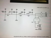
Nothing wrong beside the picture is upside down 🙂Hi Guys,
Was looking for the above schematic & came across this, is it a mistake or ???
Thks
And no need for a double pole switch, to cut the heater one pole is enough.
Mona
Oooops, Thanks Ketje it's the first time that I've seen HV taken off from filament supply.
Is there any advantage to be had ?
Thank you
Is there any advantage to be had ?
Thank you
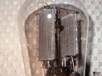
As you can see the full wave rectifier tube contains two individual tube diode within one envelop (this is mesh anode AZ1, there are more visible the "cathode", which is the heater).
The two heater end is connected together at the base.
The full wave transformer secondary has centre trap (CT), which is connected to negative ("ground") part of PSU (usually at the first capacitor negative pole).
The CT secondary "far" ends swings opposite phase, so in half period one rectifier "tube" conduct, and in the other half the another.
Lengthwise the filament the emission is not consistent (uniform), so maybe occur the difference of potential.
If you have centered filament (some tube has), the trimming is solved, if you don't the centered filament supply coil is the solution.
On other hand, the common mode noise suppression of two anodes (which is coming from mains trough the transformer) is better trimmed in CT coil (or filament) case.
Attachments
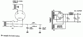
Thank you kindly Euro21 for the tutorial. I happen to have a trafo with CT for the filament, if I understand you correctly this way of connection is better ?
Many thanks again
Many thanks again
Transformers for this circuit have to have two filament windings, one for the rectifier, one for the other tubes. They are at completely different DC potentials.
> this way of connection is better ?
In principle, for the usual winding voltages, a CT on the filament winding is 1%-2% better. In practice the difference is invisible.
It shifts the cost of the wire from the assembler to the winder. In the cut-throat world of 1930s radio, that was important.
In principle, for the usual winding voltages, a CT on the filament winding is 1%-2% better. In practice the difference is invisible.
It shifts the cost of the wire from the assembler to the winder. In the cut-throat world of 1930s radio, that was important.
Attachments

- Home
- Amplifiers
- Power Supplies
- AZ1 power supply Q