lol.... nice methods there, but not common i suppose ? (stud-like component ?) hm... isopropanol works as flux ? X.x
I cheated with an amp once and cut the heatsink in half and put npn's on one heatsink and pnp's on the other. The heatsinks were then bolted onto the wooden chassis without isolating tabs. Worked very well.
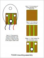
Go for a socket. Look for one of these -
An externally hosted image should be here but it was not working when we last tested it.
An externally hosted image should be here but it was not working when we last tested it.
An externally hosted image should be here but it was not working when we last tested it.
Hi Quadtech,
Very promising!
Have you used these on 200+ watts output stage? How reliable are they in the long run? I am a bit worried about the emitter contact - would it stand a couple of years of monsoon and dust?
John
Seriously?
The venerable and reliable 800 watt Peavey CS800 is full of them. The sockets are the LEAST of my worries in these amps. They work night after night in smoke, dirty night clubs, and ask little other than cleaning out the fan now and then. The amps get slammed around during setup and tear down, plus bouncing down the highway in equipment trucks.
The venerable and reliable 800 watt Peavey CS800 is full of them. The sockets are the LEAST of my worries in these amps. They work night after night in smoke, dirty night clubs, and ask little other than cleaning out the fan now and then. The amps get slammed around during setup and tear down, plus bouncing down the highway in equipment trucks.
Guitar,
you need not solder the collector / case of a TO-3!
This is the way I did it - and: this is perfect.
View attachment 242562
Best regards - Rudi_Ratlos
This is nice photo. It is easy to solder the pins on top of the PCB but if you have lines also on the other side of the PCB, how do you make sure that it is soldered too? You cannot see there. My PCB is so old that even the via is not connected both sides. How do you make sure that the other side of the PCB is also soldered properly?
This is nice photo. It is easy to solder the pins on top of the PCB but if you have lines also on the other side of the PCB, how do you make sure that it is soldered too? You cannot see there. My PCB is so old that even the via is not connected both sides. How do you make sure that the other side of the PCB is also soldered properly?
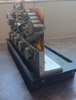
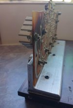
When it comes to power transistors mounted onto a heatsink, there should not be any vias on the top of the PCB, as this is clamped hard up against the bottom of the aluminium plate (TO-3 and mica on top of plate) with the pins and bolt holes going through holes in the alu and PCB. The picture Rudi shows is exactly how it needs to be done. I have also attached pictures of my Bedini 25.25 mounts original mounting.
Kevin
Attachments
Yes, the aluminium plate(collector) is clear but what I especially meant was emitter and base. Heatsink is blocking the view so you cannnot inspect result of the soldering.
Crinkle washers and solder tag on the mounting bolt is how to do it. But the whole thing
is a bit of a bodge, and its one of the reasons TO3 died out as flat packages like TO247
are far easier to work with and compact and give many more mounting options.
BTW soldering the case won't damage the chip unless you really overdo it, silicon is more robust than that when not powered.
is a bit of a bodge, and its one of the reasons TO3 died out as flat packages like TO247
are far easier to work with and compact and give many more mounting options.
BTW soldering the case won't damage the chip unless you really overdo it, silicon is more robust than that when not powered.
Handel, I always tin the pads lightly before trying to put the TO-3 in place, and then soldering to the base or emitter is much easier. the solder should not penetrate through the PCB as it may flow too far and cause a short to the sink. As I said in my post above there should not be any traces on the top side of the board, so there is nothing to worry about.
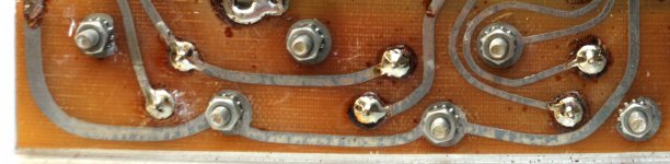
Close up view of soldered pads for three of the TO-3s.
Close up view of soldered pads for three of the TO-3s.
Attachments
No need to worry about penetrating solder at the base and emitter holes. For convenience I always drill all the holes to the same diameter of 4 mm that suits the collector insulation bushes. It's very unlikely for the solder to go that far. Hence I've never encountered any issues that could be traced from that.
Best regards!
Best regards!
The problem with soldering to the case is it will be oxidised so wont solder well.
I usually attach the collectors from a pad beneath the pcb through a bolt with a plastic bush around it to stop it shorting.
I usually attach the collectors from a pad beneath the pcb through a bolt with a plastic bush around it to stop it shorting.
- Home
- Design & Build
- Construction Tips
- soldering a TO-3 transistor technique ? (problem for me)