Hello,
after finishing a long recap and resistor upgrade on my NAD 304, I was following the alignement procedure for offset and idling current.
I did it one time and after listening some music for 10 minuts, I disconnected the speakers for a 2nd and final adjustment. While I was doing it the wire connected to the TP301 touched the metal case ( ground) of the amp, before I had the time to move it I saw some sparks.
Now the trimpot turns without any change in the idling current, it always shows something around 0.01 mV, on both channels same stuff.
I thought the amp was ready for the bin , but actually I connected to a pair of "suicide speaker" and it works.
I'm still worried about the idling current, do you have any idea of what happened? What component could be faulty ?
I tested the 10k pots with a multimeter and they seems ok.
Any help is welcome
Max
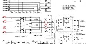
Here a detail of the schematic withh the TP301 and the bias trim highlighted detail schema nad 304.pdf - Google Drive
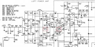
here the service manual with the full schematic nad_304_sm_2.pdf - Google Drive
after finishing a long recap and resistor upgrade on my NAD 304, I was following the alignement procedure for offset and idling current.
I did it one time and after listening some music for 10 minuts, I disconnected the speakers for a 2nd and final adjustment. While I was doing it the wire connected to the TP301 touched the metal case ( ground) of the amp, before I had the time to move it I saw some sparks.
Now the trimpot turns without any change in the idling current, it always shows something around 0.01 mV, on both channels same stuff.
I thought the amp was ready for the bin , but actually I connected to a pair of "suicide speaker" and it works.
I'm still worried about the idling current, do you have any idea of what happened? What component could be faulty ?
I tested the 10k pots with a multimeter and they seems ok.
Any help is welcome
Max
Here a detail of the schematic withh the TP301 and the bias trim highlighted detail schema nad 304.pdf - Google Drive
here the service manual with the full schematic nad_304_sm_2.pdf - Google Drive
While I was doing it the wire connected to the TP301 touched the metal case ( ground) of the amp, before I had the time to move it I saw some sparks.
TP301(+38V rail supply) shorted to ground then the +/- 38V rail supply fuses F803 / F804 maybe burned to open circuit, please check them and measure the high(+ / - 54V) and low (+ / - 38V) rail supply voltage, to check the voltage is correct or not.
Attachments
Hi Patrick, thank you for your help.
Fuses are ok. I tested the 38V on big caps C804 and C805 (it's 38,8 on one and 39 on the other). For the 54V I'm a bit confused, I tried with the black probe of multimeter on the green cable under the board (on the diagram it shows ground) and with the red probe on P82 then P84, 81 and 85 they all go to the fuses, but I couldn't read any significant tension. I did something wrong? where should I put the black probe?
Anyway it's very strange, because as I already said if I put speakers the amp seems to work.
I tried to unsold and test the Q317 which seems to be a transistor for the bias and it was perfectly working.
I was able to test 56v on C914 - C915 and 26V on C912 -C 913all seems ok.
I rechecked bias and the problem is still there (never know, sometimes things go back in order all alone).
Any idea?
Thaks again.
Your testing points are not correct.
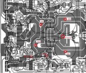
Please look at the diagram, it is the PCB layout but viewed from the component side, you can measure the +/- 38V on the big caps and +/- 54V on the medium caps next to the big caps, I marked the ground point between the big caps.
Please measure the below "four" voltages, the black probe always connected to the ground, the red probe on the medium caps test for +/- 54V, then red probe on TP301 and TP303.
Attachments
Last edited:
Thank you for the picture.
C804 38.76V
C805 -39.00V
C803 61.40V
C806 -61.60V
TP301 38.37
TP303 38.34
Max
C804 38.76V
C805 -39.00V
C803 61.40V
C806 -61.60V
TP301 38.37
TP303 38.34
Max
C804 38.76V
C805 -39.00V
C803 61.40V
C806 -61.60V
TP301 38.37
TP303 38.34
Max
Your amp power supply voltages are good and normal and your amp seems working normal.
Maybe your bias measuring method is not correct. You tested TP301 and TP303 voltages(But TP303 voltage should be higher than TP301) and there is a small voltage difference between them and this voltage difference actually is the bias voltage of this channel.
You try to set bias like this, the black probe on TP301 the red probe on TP303 and turn the VR303 for setting the correct bias.
Last edited:
This is the methos I'm using for bias measuring. A few moments before I caused the sparks I could read 5.5mV (or something around it), and now it's something around 0.01mV.
I also thought the multimeter could be wrong, but when I measure the offset it gives me coherent reading (about I can set it around 1mv).
I'm scared this thing could create damages to other components. Moreover I read somewhere that very low bias could be no good for sound.
Anyway thank you very moch for your patience and support.
Max
I tested the 10k pots with a multimeter and they seems ok.
The bias VR is VR303 and it is a 1K pot not a 10K.
TP301 38.37
TP303 38.34
Bias voltage = TP301-TP303 = 38.37-38.34 = 0.03V
If you like to try, when you turn the bias VR303, you can measure the voltage on resistor R351 330 ohm which voltage will be changed at the same time and this can confirm the bias circuit is correct.
one more dumb question, red probe and black probe before and after the resistor?
I have tried this way and when I turn the VR303 I can see a variation from about 400mV to 700mV
regards
one more dumb question, red probe and black probe before and after the resistor?
I have tried this way and when I turn the VR303 I can see a variation from about 400mV to 700mV
regards
You put the red probe and black probe on the resistor R351 330 ohm legs, no need care the resistor direction, a positive or negative voltage readout is ok, just care the voltage variation.
the variation is from 400mV to 740mV (approx)
Thanks
The voltage is low, please set the vr to1k first and measure Q317 C and E pins voltage, it should be around 2.8v.
- Home
- Amplifiers
- Solid State
- NAD 304 bias problem