A brief history of the project:
-------------------------------
This small project has the objective of to create a delay in time of
about 5-6 seconds in order to provide sufficient time to the main amplifier to
stabilize its internal voltages and currents, as it is fully DC coupled. One
of the conditions of the designing, was to take advantage and give use to some
particular compactron tubes I have at home, like 12AL11, 6G11, 6BF11, 6T10, et
al. All them have a sharp cutoff pentode unit designed originally for the FM
quadrature detection/demodulation, with all its electrodes tied to an independent
pin on the base, including the suppressor grid. Some of them has an internal
shield tied also to a pin or to the cathode (earthed in this project) Also,
the suppressor has been designed to take good control over the anode current.
The tetrode section is a beam unit, similar in some aspects to the 6AQ5 while
the pentode unit resembles the 6DT6 or 6AS6 in the 7 pin tubes.
The first knowledge about a circuit of this kind I got, was written on
a patent from Burrows (3). There, he said that a single pentode may be conected
in such a way that behaves like a Schmitt trigger (2), originally done with a
dual triode unit, their cathodes joined and grounded through a common resistor,
and with a resistive attenuator from one plate to the other grid to provide DC
coupling between the two stages. There is a free grid to trigger it in the mono
or bistable modes or provide a variable DC voltage level to make it oscillate
in the astable mode. This will result in a regenerative amplifier with two only
stable states, depending on the signal that is feed to the circuit, or, eventually,
make it to oscillate. In his idea, a resistive coupling between the screen and
the suppressor grids would give the desired (necessary) regenerative coupling,
as one may think a pentode as two triodes composed by the cathode, control grid
and screen grid and the other by the virtual cathode between the suppressor and
the screen, being the former the second (Triode) grid and the anode, the plate
of the second stage. He gives in his patent, voltages and resistances values
for his set up. I tried a similar connection to my pentodes, and made a large
reckoning to obtain the values of the passive components needed to put the
circuit to job. But it was a complete disaster. There wasn't any bistability,
nor hysteretic behavior. After it, I downloaded the 6AS6 datasheet and reverse
engineered the circuit, but it was very unclear (and still is) for me how the
author could do it to perform. My attention was focused in the unbypassed cathode
resistor he used, but no description of its functionality in the scheme. I tryed
the setup as a Phantastron, feeding the grid from the plate by means of a small
capacitor and it performed reasonably well, so I was near the objective but I
didn't get it.
So, I searched in the literature I have, and in the Seely's (4) book
it is said that such a connection was discovered by an Engineer called H. J.
Reich, who also is mentioned in the above mentioned patent, and made public in
an article written in the "Review of Scientific Instruments" near 1939, but it
is restricted only for paid subscriptors. So I made and extensive and deep
internet searching for more info, supposing that some kind of info must be
elsewhere, because those big genius usually published or teach their knowledge
around the society. I found that he also wrote an article in one of the "Electronics"
magazine issue of 1939 (5), I got the article in the americanradiohistory.com
website and printed it. I took a deep read of it, and effectively, Reich
explains that almost all pentodes have some serious irregularities in their
IG2 = f(EG2) characteristic, mainly at lower plate voltages. It is far from a
straight line, and has loops or buckles in them, and in certain way are like
to the negative resistance seen in the neon bulb I = f(V) characteristic. I knew
about this straneous behavior but I didn't link them to any kind of bistability
or the like. The secret was to find them in my pentodes. Then, I prepared a jig
in which the cathode of my tube was grounded directly, the control grid biased
thanks to contact potential using a single 10MΩ resistor to cathode, grounding
the suppressor too, the screen tied to +275V with a fixed 10KΩ resistor plus a
100KΩ pote wired as variable resistor (Rheostat). The beam unit was momentarily
unused. The plate was loaded with a 1W resistor to the same power source, and
hooked the oscilloscope probes, one to the plate and the other to the screen
electrode. Surprisingly, the irregularity was there: near 80V of screen bias,
and slowly rotating the pote, a steep of about 15V appeared and it refects in
the anode voltage too. I checked four 12AL11 tubes in the same way, with another
four different values of plate load resistor. I initially I mistrusted from the
pote, and double checked it for deeps in the carbon trace with and ohmmeter and
with a resistor from screen to ground (Simulating screen current), removing the
12AL11 from its socket and the jump didn't appear. So, effectively, it was the
pentode itself who was creating the jump in the screen grid voltage to current
function. So, Reich was true in his affirmation. The only that remain was to
couple the screen to the suppressor removing the earthing piece of wire, and
computing a pair of proper resistor values that, with the jump voltage differences,
can carry the suppressor below the plate current cutoff voltage, (near -4V as the
datasheet sais), or free the anode current, near 0V or perhaps +1V. This table
resumes what I found for the four 12AL11's, numbered arbitrarily:

I also tried 100KΩ anode resistor loads, but at such low values, the
jump vanishes too much to be of interest or importance. The next steep was to
check some of the other type of tubes I have at hand, like the 6BF11 and 6T10.
Rearranging the socket wiring, I found that the 6BF11 has a more pronounced
irregularity and was the final choice, and also performs good with 100KΩ anode
load. Fortunately the value of screen dropping resistor always were about 45
to 50Kê, for the entire tube lot, and a 47KΩ @ 2W was the final chose value.
Then I coupled the screen to the suppressor via a resistor divider and
a small mica cap (220pF) and to the negative rail of -275V. A 6AL5 diode was
used from suppressor to ground to prevent the last to make too positive. A
300Kê small preset was included to adjust the optimum value. I was very happy
when accidentally the solder iron cable (A Taiyo SL20/200 with an external
TRIAC dimmer) fall near the circuit (The white and blue cotton covered saw in
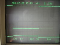
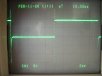
some of the pics) and the pentode acted a true Schmitt trigger (Some pics below).
The oscillograms show the anode, screen and supressor waveforms perfectly
triggered and syncronized to the spikes generated by the TRIAC dimmer, their
amplitudes and times, taking into account that the oscilloscope's test leads
has a X10 attenuation not shown in the read out, and that line frequency here
is 50Hz (20mS). The coupling of the cable to the circuit appeared to be more
sensible when placed near the screen-suppressor network that with coupling close
to the grid bias resistor. Burrows used both grid and suppressor coupling trough
germanium diodes.
Once that the Schmitt part of the circuit was OK, the next steep was
to couple a time constant to the input in a manner like a CD40106/74HC14,
hooking a 240VAC 9Kê relay to the beam power unit, a resistive divider from
the pentode anode to the beam unit's control grid. Initially I though to make
the pentode to act in a similar manner than in a device called by F. C. Williams
"Multiar" (1), which uses a transformer to take the regenerative fast action
and a diode as a switch. Also, a small 470pF mica capacitor was paralleled to
provide fast transient coupling from plate to grid. The way in which the time
constant and the values of the elements changed with time and circuit, but
finally I added another 6BV8 tube composed by two independent diodes and a
triode with æ ÷ 33. However, a small problem soonly arise. The triode was used
as cathode follower to provide high input resistance to the time constant network
and low impedance to the switching diode, and the diodes were wired to clamp
the grid voltage between -50V and ground provided by a resistive atenuattor from
the negative bus. But as the plate was to +275V then, the tube cuts off near
-20 or -25V and the full excursion of the voltage swing at the grid wasn't
transferred to the cathode. So, once again, I changed the socket and migrate to
another compactron tube 8B10. As I have only 6.3V heaters, I used it with 6.3V
temporarily with no apparent bright differences or notable performance loose.
(Furtherly I got some 6B10's and replaced them). This compactron has two triodes
like a 12AU7 and two common cathode diodes like a 6AL5 (or the 6CN7). Then, one
of this diodes was used to clamp the grid of the cathode follower to ground,
the other to the same task in the 6BF11's suppressor. The slicer (6) so formed,
has the objective of to take advantage only the fastest part of the exponential
voltage/time rundown waveform where it evolutes quickier and a more defined
behavior is expected, and limit the grid (And the cathode) swing to safe values
as the heater is grounded and the final voltage of the capacitor in absence of
the slicer is near the negative rail. Having freed a diode from the 6AL5, it
was become available to use it as the switch. The second triode was used as a
voltage source, hooking a neon lamp at its grid, biased with 220Kê to the +275V,
and feeding the anode of the follower with this lower voltage value. So, by
this moment the screen of the beam power section was biased with 100KΩ to the
positive rail and soonly I took the idea of to replace again the 6AL5 with the
6BV8 and make a rudimentary voltage regulator moving the neon to the negative
side, providing fixed clamping levels for the grid, and at the same time with
the triode inside the 6BV8 and one of the 6B10 as a "See Saw" voltage stabilizer,
and also feed from this to the screen of the beam power section. The voltage
at the screen is about 60V and suffices to cutout the anode current with -12V
accordingly to the tube data sheet, although the excursion available at the
control grid is of near 90V. But the 60V was OK for the current I need to drive
the relay coil. The current drawn by the relay coil is (275V - 60V) / 9KΩ, or
24mA, well under the tetrode capacities. Then I finally arrived to the actual
configuration (The bottomed voltage of the beam power unit is near 60V).
How it works:
-------------
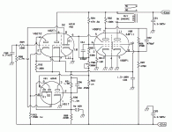
R80 and C80 are the time constants, tied from negative bus and ground.
R89 limits the current drawn by the diode slicer and cuts out any voltage
above ground and below the neon's voltage, near 60-65VDC, negative to ground.
This network also is found in many CMOS devices to prevent ESD and dangerous
levels at their inputs. V82 is a follower, and the diode at its cathode is the
main switch. When powering it on, the pentode 6BF11 starts conducting full anode
current, with the suppressor biased at ground level imposed by the resistive
network and the diode. Anode voltage is low, and the coupling divider to beam
power section maintains the grid well below the cutoff bias, near -90V. As C80
is going more negative (The heaters are lighted some seconds ago), the cathode
follows the grid potential, and diode D2 is cut off because the volage at the
join of P80 and R83 is several volts negative. As well as the grid and cathode
of the follower are going sufficiently negative to direct bias D2, it starts
conducting and pushes the hysteretic network to a still more negative potential.
The Schmitt-like circuit quickly trips (Regeneratively) and the suppressor goes
very negative (-20V) cutting plate current and deriving the electron stream
flow to the screen only, as the control grid here only decides how many current
is able to flow but doesn't participate in the timing mechanism. The fact that
the pentode's cathode current never is fully cutout difficult that its cathode
develop a oxide layer being too many time without cathode current (6). When the
current of the plate of the pentode is cut out, the anode voltage rises violently
and carries the beam power unit in the grid base making it conductive and
energizing the relay at its anode. V81 and V82 (as already said) only make a
rudimentary voltage regulator for the follower and the beam section's screen.
P80 adjust the trip level and the initial conditions of the circuit. C86 makes
with the relay coil a loosy tuned circuit and self damps the spikes at the
moment of removing anode and relay current, and a diode isn't necessary here
because of the natural ruggedness of tubes.
You may feel to find similarities in the circuit with the hysteretic
scheme that can be build using a comparator or an opamp, feeding the non
inverting input with part of the output voltage swing, maintaining the other
input to a reference potential (In my case the control grid), and effectively
is seems similar. However, the mechanism is very different, as here there isn't
any amplification deliberately did to the signal, using a peculiarity of the
pentode's screen characteristic, and there is more similar with the negative
resistance of a neon pilot lamp, or in a SS device, nearest to a DIAC than a
trigger made with opamps.
All this stuff may be made simply wiring a capacitor in series to the
relay coil and feeding it with DC, when the cap charges sufficiently, the relay
liberates its armature and a change in circuit is done. But my idea was also
to explore old knowledge now almost useless.
R96 and the pushbutton discharges the cap during the experimental period,
simplifying the development of the circuit and being a test method.
I didn't check it for repeatability, linearity or constancy of the
timed circuit, as for the purpose for it was designed, those parameters are
unnecessary and irrelevant. Only a small delay of time to switch a relay was
needed.
The circuit uses only two compactron tubes, a noval unit and no SS at
all. Current drawn from the Ebb line is less than 30mA with the relay energized,
a couple of mA's in the negative rail, and a pair of amperes at 6.3VAC.
Conclusions:
------------
I built a timed relay device that prevents noises and the saturation of
an output autotransformer while the DC coupled audio amplifier is accomodating
its internal parameters, using multiple compactron tubes which was originally
made for FM demodulation and power amplifier in TV sets, and taking advantage
of the pentode's screen grid characteristic to make a hysteretic switching
circuit.
References:
-----------
1) US 2,540,093 from F. C. Williams (06/02/51);
2) Otto Schmitt, "A Termionic Trigger", Proceedings of the IRE;
3) US 2,872,572 from J. L. Burrows, (03/02/59);
4) Samuel Seely "Electron Tube Circuits", McGraw-Hill Book Company, 1950;
5) H. J. Reich, "Trigger Circuits", Electronics (08/39);
6) J. Millman and H. Taub "Pulse and Digital Circuits", McGraw-Hill Book
Company, 1956.
-------------------------------
This small project has the objective of to create a delay in time of
about 5-6 seconds in order to provide sufficient time to the main amplifier to
stabilize its internal voltages and currents, as it is fully DC coupled. One
of the conditions of the designing, was to take advantage and give use to some
particular compactron tubes I have at home, like 12AL11, 6G11, 6BF11, 6T10, et
al. All them have a sharp cutoff pentode unit designed originally for the FM
quadrature detection/demodulation, with all its electrodes tied to an independent
pin on the base, including the suppressor grid. Some of them has an internal
shield tied also to a pin or to the cathode (earthed in this project) Also,
the suppressor has been designed to take good control over the anode current.
The tetrode section is a beam unit, similar in some aspects to the 6AQ5 while
the pentode unit resembles the 6DT6 or 6AS6 in the 7 pin tubes.
The first knowledge about a circuit of this kind I got, was written on
a patent from Burrows (3). There, he said that a single pentode may be conected
in such a way that behaves like a Schmitt trigger (2), originally done with a
dual triode unit, their cathodes joined and grounded through a common resistor,
and with a resistive attenuator from one plate to the other grid to provide DC
coupling between the two stages. There is a free grid to trigger it in the mono
or bistable modes or provide a variable DC voltage level to make it oscillate
in the astable mode. This will result in a regenerative amplifier with two only
stable states, depending on the signal that is feed to the circuit, or, eventually,
make it to oscillate. In his idea, a resistive coupling between the screen and
the suppressor grids would give the desired (necessary) regenerative coupling,
as one may think a pentode as two triodes composed by the cathode, control grid
and screen grid and the other by the virtual cathode between the suppressor and
the screen, being the former the second (Triode) grid and the anode, the plate
of the second stage. He gives in his patent, voltages and resistances values
for his set up. I tried a similar connection to my pentodes, and made a large
reckoning to obtain the values of the passive components needed to put the
circuit to job. But it was a complete disaster. There wasn't any bistability,
nor hysteretic behavior. After it, I downloaded the 6AS6 datasheet and reverse
engineered the circuit, but it was very unclear (and still is) for me how the
author could do it to perform. My attention was focused in the unbypassed cathode
resistor he used, but no description of its functionality in the scheme. I tryed
the setup as a Phantastron, feeding the grid from the plate by means of a small
capacitor and it performed reasonably well, so I was near the objective but I
didn't get it.
So, I searched in the literature I have, and in the Seely's (4) book
it is said that such a connection was discovered by an Engineer called H. J.
Reich, who also is mentioned in the above mentioned patent, and made public in
an article written in the "Review of Scientific Instruments" near 1939, but it
is restricted only for paid subscriptors. So I made and extensive and deep
internet searching for more info, supposing that some kind of info must be
elsewhere, because those big genius usually published or teach their knowledge
around the society. I found that he also wrote an article in one of the "Electronics"
magazine issue of 1939 (5), I got the article in the americanradiohistory.com
website and printed it. I took a deep read of it, and effectively, Reich
explains that almost all pentodes have some serious irregularities in their
IG2 = f(EG2) characteristic, mainly at lower plate voltages. It is far from a
straight line, and has loops or buckles in them, and in certain way are like
to the negative resistance seen in the neon bulb I = f(V) characteristic. I knew
about this straneous behavior but I didn't link them to any kind of bistability
or the like. The secret was to find them in my pentodes. Then, I prepared a jig
in which the cathode of my tube was grounded directly, the control grid biased
thanks to contact potential using a single 10MΩ resistor to cathode, grounding
the suppressor too, the screen tied to +275V with a fixed 10KΩ resistor plus a
100KΩ pote wired as variable resistor (Rheostat). The beam unit was momentarily
unused. The plate was loaded with a 1W resistor to the same power source, and
hooked the oscilloscope probes, one to the plate and the other to the screen
electrode. Surprisingly, the irregularity was there: near 80V of screen bias,
and slowly rotating the pote, a steep of about 15V appeared and it refects in
the anode voltage too. I checked four 12AL11 tubes in the same way, with another
four different values of plate load resistor. I initially I mistrusted from the
pote, and double checked it for deeps in the carbon trace with and ohmmeter and
with a resistor from screen to ground (Simulating screen current), removing the
12AL11 from its socket and the jump didn't appear. So, effectively, it was the
pentode itself who was creating the jump in the screen grid voltage to current
function. So, Reich was true in his affirmation. The only that remain was to
couple the screen to the suppressor removing the earthing piece of wire, and
computing a pair of proper resistor values that, with the jump voltage differences,
can carry the suppressor below the plate current cutoff voltage, (near -4V as the
datasheet sais), or free the anode current, near 0V or perhaps +1V. This table
resumes what I found for the four 12AL11's, numbered arbitrarily:
I also tried 100KΩ anode resistor loads, but at such low values, the
jump vanishes too much to be of interest or importance. The next steep was to
check some of the other type of tubes I have at hand, like the 6BF11 and 6T10.
Rearranging the socket wiring, I found that the 6BF11 has a more pronounced
irregularity and was the final choice, and also performs good with 100KΩ anode
load. Fortunately the value of screen dropping resistor always were about 45
to 50Kê, for the entire tube lot, and a 47KΩ @ 2W was the final chose value.
Then I coupled the screen to the suppressor via a resistor divider and
a small mica cap (220pF) and to the negative rail of -275V. A 6AL5 diode was
used from suppressor to ground to prevent the last to make too positive. A
300Kê small preset was included to adjust the optimum value. I was very happy
when accidentally the solder iron cable (A Taiyo SL20/200 with an external
TRIAC dimmer) fall near the circuit (The white and blue cotton covered saw in
some of the pics) and the pentode acted a true Schmitt trigger (Some pics below).
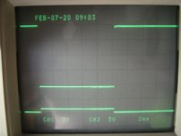
The oscillograms show the anode, screen and supressor waveforms perfectly
triggered and syncronized to the spikes generated by the TRIAC dimmer, their
amplitudes and times, taking into account that the oscilloscope's test leads
has a X10 attenuation not shown in the read out, and that line frequency here
is 50Hz (20mS). The coupling of the cable to the circuit appeared to be more
sensible when placed near the screen-suppressor network that with coupling close
to the grid bias resistor. Burrows used both grid and suppressor coupling trough
germanium diodes.
Once that the Schmitt part of the circuit was OK, the next steep was
to couple a time constant to the input in a manner like a CD40106/74HC14,
hooking a 240VAC 9Kê relay to the beam power unit, a resistive divider from
the pentode anode to the beam unit's control grid. Initially I though to make
the pentode to act in a similar manner than in a device called by F. C. Williams
"Multiar" (1), which uses a transformer to take the regenerative fast action
and a diode as a switch. Also, a small 470pF mica capacitor was paralleled to
provide fast transient coupling from plate to grid. The way in which the time
constant and the values of the elements changed with time and circuit, but
finally I added another 6BV8 tube composed by two independent diodes and a
triode with æ ÷ 33. However, a small problem soonly arise. The triode was used
as cathode follower to provide high input resistance to the time constant network
and low impedance to the switching diode, and the diodes were wired to clamp
the grid voltage between -50V and ground provided by a resistive atenuattor from
the negative bus. But as the plate was to +275V then, the tube cuts off near
-20 or -25V and the full excursion of the voltage swing at the grid wasn't
transferred to the cathode. So, once again, I changed the socket and migrate to
another compactron tube 8B10. As I have only 6.3V heaters, I used it with 6.3V
temporarily with no apparent bright differences or notable performance loose.
(Furtherly I got some 6B10's and replaced them). This compactron has two triodes
like a 12AU7 and two common cathode diodes like a 6AL5 (or the 6CN7). Then, one
of this diodes was used to clamp the grid of the cathode follower to ground,
the other to the same task in the 6BF11's suppressor. The slicer (6) so formed,
has the objective of to take advantage only the fastest part of the exponential
voltage/time rundown waveform where it evolutes quickier and a more defined
behavior is expected, and limit the grid (And the cathode) swing to safe values
as the heater is grounded and the final voltage of the capacitor in absence of
the slicer is near the negative rail. Having freed a diode from the 6AL5, it
was become available to use it as the switch. The second triode was used as a
voltage source, hooking a neon lamp at its grid, biased with 220Kê to the +275V,
and feeding the anode of the follower with this lower voltage value. So, by
this moment the screen of the beam power section was biased with 100KΩ to the
positive rail and soonly I took the idea of to replace again the 6AL5 with the
6BV8 and make a rudimentary voltage regulator moving the neon to the negative
side, providing fixed clamping levels for the grid, and at the same time with
the triode inside the 6BV8 and one of the 6B10 as a "See Saw" voltage stabilizer,
and also feed from this to the screen of the beam power section. The voltage
at the screen is about 60V and suffices to cutout the anode current with -12V
accordingly to the tube data sheet, although the excursion available at the
control grid is of near 90V. But the 60V was OK for the current I need to drive
the relay coil. The current drawn by the relay coil is (275V - 60V) / 9KΩ, or
24mA, well under the tetrode capacities. Then I finally arrived to the actual
configuration (The bottomed voltage of the beam power unit is near 60V).
How it works:
-------------
R80 and C80 are the time constants, tied from negative bus and ground.
R89 limits the current drawn by the diode slicer and cuts out any voltage
above ground and below the neon's voltage, near 60-65VDC, negative to ground.
This network also is found in many CMOS devices to prevent ESD and dangerous
levels at their inputs. V82 is a follower, and the diode at its cathode is the
main switch. When powering it on, the pentode 6BF11 starts conducting full anode
current, with the suppressor biased at ground level imposed by the resistive
network and the diode. Anode voltage is low, and the coupling divider to beam
power section maintains the grid well below the cutoff bias, near -90V. As C80
is going more negative (The heaters are lighted some seconds ago), the cathode
follows the grid potential, and diode D2 is cut off because the volage at the
join of P80 and R83 is several volts negative. As well as the grid and cathode
of the follower are going sufficiently negative to direct bias D2, it starts
conducting and pushes the hysteretic network to a still more negative potential.
The Schmitt-like circuit quickly trips (Regeneratively) and the suppressor goes
very negative (-20V) cutting plate current and deriving the electron stream
flow to the screen only, as the control grid here only decides how many current
is able to flow but doesn't participate in the timing mechanism. The fact that
the pentode's cathode current never is fully cutout difficult that its cathode
develop a oxide layer being too many time without cathode current (6). When the
current of the plate of the pentode is cut out, the anode voltage rises violently
and carries the beam power unit in the grid base making it conductive and
energizing the relay at its anode. V81 and V82 (as already said) only make a
rudimentary voltage regulator for the follower and the beam section's screen.
P80 adjust the trip level and the initial conditions of the circuit. C86 makes
with the relay coil a loosy tuned circuit and self damps the spikes at the
moment of removing anode and relay current, and a diode isn't necessary here
because of the natural ruggedness of tubes.
You may feel to find similarities in the circuit with the hysteretic
scheme that can be build using a comparator or an opamp, feeding the non
inverting input with part of the output voltage swing, maintaining the other
input to a reference potential (In my case the control grid), and effectively
is seems similar. However, the mechanism is very different, as here there isn't
any amplification deliberately did to the signal, using a peculiarity of the
pentode's screen characteristic, and there is more similar with the negative
resistance of a neon pilot lamp, or in a SS device, nearest to a DIAC than a
trigger made with opamps.
All this stuff may be made simply wiring a capacitor in series to the
relay coil and feeding it with DC, when the cap charges sufficiently, the relay
liberates its armature and a change in circuit is done. But my idea was also
to explore old knowledge now almost useless.
R96 and the pushbutton discharges the cap during the experimental period,
simplifying the development of the circuit and being a test method.
I didn't check it for repeatability, linearity or constancy of the
timed circuit, as for the purpose for it was designed, those parameters are
unnecessary and irrelevant. Only a small delay of time to switch a relay was
needed.
The circuit uses only two compactron tubes, a noval unit and no SS at
all. Current drawn from the Ebb line is less than 30mA with the relay energized,
a couple of mA's in the negative rail, and a pair of amperes at 6.3VAC.
Conclusions:
------------
I built a timed relay device that prevents noises and the saturation of
an output autotransformer while the DC coupled audio amplifier is accomodating
its internal parameters, using multiple compactron tubes which was originally
made for FM demodulation and power amplifier in TV sets, and taking advantage
of the pentode's screen grid characteristic to make a hysteretic switching
circuit.
References:
-----------
1) US 2,540,093 from F. C. Williams (06/02/51);
2) Otto Schmitt, "A Termionic Trigger", Proceedings of the IRE;
3) US 2,872,572 from J. L. Burrows, (03/02/59);
4) Samuel Seely "Electron Tube Circuits", McGraw-Hill Book Company, 1950;
5) H. J. Reich, "Trigger Circuits", Electronics (08/39);
6) J. Millman and H. Taub "Pulse and Digital Circuits", McGraw-Hill Book
Company, 1956.
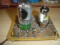
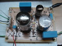
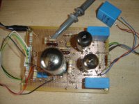
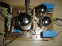
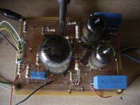
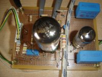
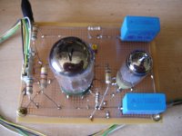
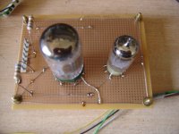
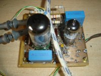
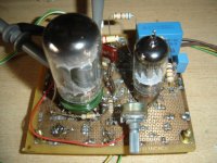
Some pics
Here are some images from the very start.
Here are some images from the very start.
Attachments
-
 Delay 01.JPG143.5 KB · Views: 109
 -
 Delay 10.JPG149.9 KB · Views: 76
 -
 Delay 09.JPG146.5 KB · Views: 77
 -
 Delay 08.JPG153.2 KB · Views: 86
 -
 Delay 07.JPG138.2 KB · Views: 90
 -
 Delay 06.JPG147.1 KB · Views: 81
 -
 Delay 05.JPG138.9 KB · Views: 75
 -
 Delay 04.JPG139.7 KB · Views: 90
 -
 Delay 03.JPG156.6 KB · Views: 92
 -
 Delay 02.JPG145.9 KB · Views: 117
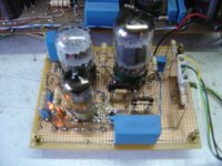
More pics
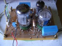
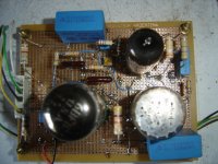
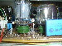
Still more photos and oscillograms.
Still more photos and oscillograms.
Attachments
-
 Delay 14.JPG136.4 KB · Views: 84
 -
 Delay 13.JPG150.6 KB · Views: 83
 -
 Delay 12.JPG151.9 KB · Views: 88
 -
 Delay 11.JPG136.6 KB · Views: 93
 -
 Delay Oscilo 01.JPG141.7 KB · Views: 87
 -
 Delay Oscilo 02.JPG123 KB · Views: 88
 -
 Delay Oscilo 03.JPG132.2 KB · Views: 64
 -
 Delay Oscilo 04.JPG140.3 KB · Views: 70
 -
 Delay Oscilo 05.JPG126.5 KB · Views: 75
Last edited:
Great.
On my DC coupled PP, I've build a PS delayed board, and I let the tube warm up for 40 secondes, then I activate the voltage doubler, which also has a 200 R thermistor build in.
The B+ comes slowly, within 2 secondes I would say, which is slow from an electrical point of view.
It has worked nicely so far, without noise or pop at activation, and the DC couplage is immediately stable. Before that it was scary.
As my amp is fully DC coupled and has large time constants to enable lowest frequency control, the time is about 20 seconds actually. I am very happy with the operation of this monster. Now I am planning a new one with PWM control of the current trough the relay.
Why not just switch heather on and off ?
I meant the heather of the tube driving the relay.
But of course a 555 could do the job as well🙂
Last edited:
The secondary object of this project, was to learn something more. I learned very much doing it. It is obvious that there are billions of easiest ways to do the job: a simple capacitor in series with the relay coil, energized with DC. But this is a trivial one and lacks any attempt to study a new thing. The readings were also very interesting and added lots to my brain.
Here is a short video showing both signals, anode and cathode of the diode switch (Comparator) V81 D1. Upper trace is the ramp, and bottom is the hysteretic input to V80. At the firsts, few seconds the circuit is powered on, and voltages established. Near the end, when both traces collapse, a click sound is heard and it is the activation of the relay sound.
Attachments
Last edited:
The secondary object of this project, was to learn something more. I learned very much doing it. It is obvious that there are billions of easiest ways to do the job: a simple capacitor in series with the relay coil, energized with DC. But this is a trivial one and lacks any attempt to study a new thing. The readings were also very interesting and added lots to my brain.
Obviously the strongest motivation !
Yeah, it is a toy.
Yesterday I found in the web, a book entirely dedicated to time bases generators: Time Bases ( Their Design & Development ) : O.S. Puckle : Free Download, Borrow, and Streaming : Internet Archive
When the pandemia finishes I shall try to buy it.
Yesterday I found in the web, a book entirely dedicated to time bases generators: Time Bases ( Their Design & Development ) : O.S. Puckle : Free Download, Borrow, and Streaming : Internet Archive
When the pandemia finishes I shall try to buy it.
- Home
- Amplifiers
- Tubes / Valves
- Delayed relay pentode driven
