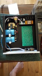
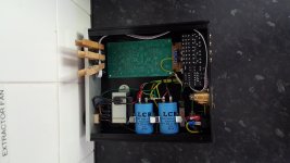
I'm just building an input selector / RCA - balanced convertor.
The case is quite tight but it does all fit.
Should I mount the meagre mains transformer at the front of the case away from the XLR connectors or just leave it where it is ?
I don't really want any more holes in the chassis than absolutely necessary.
The case is quite tight but it does all fit.
Should I mount the meagre mains transformer at the front of the case away from the XLR connectors or just leave it where it is ?
I don't really want any more holes in the chassis than absolutely necessary.
Attachments
Last edited:
You can try it first as it is now, but route that ribbon cable along the other (right) side of the chassis.
Is your right foot supposed to fit into the case too? Better have it isolated to prevent sparks.
Is your right foot supposed to fit into the case too? Better have it isolated to prevent sparks.
If you're asking it me, I cannot tell it from the picture. But then over the bottom is as good as well, and shorter if you're running out of ribbons. And your right foot?
4 relays & 4+1 wires makes sense to control them.
I would use another type of bridge (35A square faston type) and would bolt it to the chassis too. Yes and the foot fits too.
I would use another type of bridge (35A square faston type) and would bolt it to the chassis too. Yes and the foot fits too.
Depends on the thickness of the required isolation.Yes and the foot fits too.
These considerations require and approve for a separated branch: the foot-topic!
Is it a barbeque? Is it a magicians cauldron? Will this cramped dance hall be illuminated with chandeliers or mirror balls? It is less then a squire foot.
I always keep audio away from mains.
For safety and less hum pick up.
Case needs earthing as well.
For safety and less hum pick up.
Case needs earthing as well.
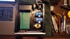
There is room for a slightly larger transformer if necessary.
I've got to play between two different voltage requirements unless I add a regulator board.
The input selector uses an LM7812 so has a maximum input of 27V.
The convertor boards need 20-0-20V.
As it stands I've got a 15-0-15V transformer which is supply an unregulated 20-0-20V supply. With the huge 4700uF caps that is fine for a pre-amp.
I might increase the transformer to 30VA and 18-0-18V and add a regulator for the 20-0-20V supplies.
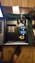
UPDATE.
I have found an 18-0-18V transformer so I will be going down the dual regulator route.
It's a tight fit but I think it will work.
I have found an 18-0-18V transformer so I will be going down the dual regulator route.
It's a tight fit but I think it will work.
Attachments
Last edited:
The 3-dimensional puzzle has been solved.
Curiously, when looking at the attached thumbnails in #11, it appears as if you're equipped with two (insulated) right feet.
Curiously, when looking at the attached thumbnails in #11, it appears as if you're equipped with two (insulated) right feet.
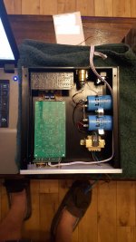
I've fitted the 30VA transformer and now all I'm waiting for is the main PCB from China.
It's a bit of a tight fit but the build looks OK to me.
It's resting against the tiled wall because I've had to glue the control knobs on, they just wouldn't sit flat on the shafts with their grub screws.
It's a bit of a tight fit but the build looks OK to me.
It's resting against the tiled wall because I've had to glue the control knobs on, they just wouldn't sit flat on the shafts with their grub screws.
Attachments
Looks good, and I notice that the tiled wall heat extractor fan is coming down into the design soon.
I've not used XLR connectors before so this is a new venture for me.
This unit is basically an RCA selector, allowing 4 x phono inputs the output of which is then converted to XLR balanced output.
This will then feed a DIY Pass Aleph 1.7.
I then have two Pass amps, the Aleph 4 and the Aleph J.
The Aleph 4 was built with single ended RCA input which I always felt was not outputting the full output it was capable of.
The Aleph J is being built as a balanced input from the outset.
I do intend on converting the Aleph 4 to a balanced input eventually.
Looking at the threads on XLR and RCA earth configurations I'm guessing that I will have to spend some time clearing earth loops.
If you look closely at the bottom right corner of the unit you will notice that I have incorporated a classic Earth Loop Breaker with a bridge rectifier / 10R / and 100nF.
Now I'm really curious about that particular circuit you've used!...which is then converted to XLR balanced output...
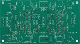
The unbalanced to balanced convertor is a bit of an unknown and a gamble.
I've bought a Chinese clone of a Kevin Gilmore design. I have no schematic, the only clue to the components is in the silk screen on the board.
I also have an IC based circuit as a back-up in case my gamble proves to be a waste of time.
The regulator board is LM317/LM337 based so can be adjusted for all eventualities.
Attachments
Last edited:
Tempting! Any pictures or references?...of an unknown and a gamble...
There are very good asym-sym converters, also without opamps.
An there are awful designs.
- Home
- Amplifiers
- Solid State
- Componment placement