Thanks Zen Mod. Not sure if this is the correct method, but I measured for continuity between the center pin on the MOSFETs and the hold-down screw. I saw no connection.
I'm ordering new ZTX parts (fingers crossed).
I'm ordering new ZTX parts (fingers crossed).
Wowbagger: Forgive my inexperience. Do I measure that from the outside pins?
Yes - the schematic shows that the middle pin is connected to the lower (outside) pin. The voltage across the outer pins is the voltage seen by the lower output devices (the ones you're measuring the bias on).
Attachments

Wowbagger: I figured the pads would be suitable. Thanks for taking the time to explain. I measure no voltage across the pads.
Since the latest development (22.9V on the output), what's the voltage across R8?
If the lower ZTX (Q3) is bad, it might be shorting to the lower rail, bringing the input on the lower MOSFETS to V- and preventing any bias current from flowing. Q3 can be removed and the amp will be functional - Q3 is a safety feature to limit peak output current, but it is not required. If you remove Q3 and the amp works again, then you've found your problem.
If the lower ZTX (Q3) is bad, it might be shorting to the lower rail, bringing the input on the lower MOSFETS to V- and preventing any bias current from flowing. Q3 can be removed and the amp will be functional - Q3 is a safety feature to limit peak output current, but it is not required. If you remove Q3 and the amp works again, then you've found your problem.
Last edited:
Q3 is removed (by virtue of diagonal cutters), and voltage is still >22V on speaker output. Bummer.
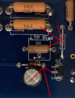
What is the voltage between the jumper R6 and the leg of D1 closest to Q2? You should see about 0.6 V
If Q2 is bad (or if there's as soldering issue), and shorting these points together, you'll get about 8.5 V over R8 and 20-ish volts on the output (according to LTSpice).
The other explanation is that Q1A isn't conducting, but that's an expensive problem...
If Q2 is bad (or if there's as soldering issue), and shorting these points together, you'll get about 8.5 V over R8 and 20-ish volts on the output (according to LTSpice).
The other explanation is that Q1A isn't conducting, but that's an expensive problem...
Attachments
Last edited:
With the negative meter lead attached to the right side of D1, it was about +600mv at startup and lowered to ~550mv after a minute.
Options:
1. Wait until you order more ZTX parts and replace Q2.
2. If you remove the jumper R30, you can use your multimeter in ammeter mode to measure if there is any current passing through Q2 by inserting your probes where the jumper was.
+ If there is ~8.5 mA, then Q2 is working, and the current isn't passing through Q1A, since you've measured 0 V on the offset pot, which follows Q1A (EDIT: Unless the pot has failed and has zero resistance). This will give 20 V + on the output. This would suggest concern about Q1A.
+ If there is 0 mA, then Q2 is your problem. (EDIT: or Q1A - if Q1A fails to conduct, then Q2 won't pass current either).
Last edited:
Wowbagger: Thanks. If I need to replace Q1A, do I need to purchase another matched quad ad replace all the JFETs?
I ordered replacement ZTX parts, which should be here tomorrow.
I ordered replacement ZTX parts, which should be here tomorrow.
Other options: with the amp off, check for continuity across the offset pot - there could be a solder short that would produce the same symptoms.
If I need to replace Q1A, do I need to purchase another matched quad ad replace all the JFETs?
Probably.
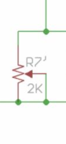
I measure 243R across R7. When I adjust the pot it doesn't change. Is that normal?
243R in that position would also give ~20V on the output. Is there another pot you can substitute in? It should change when you adjust it. I don't see any other parts other than the mosfets that would be parallel in the circuit - the pot should be the only thing between the probes, so I would expect the resistance to change.
Last edited:
I have another 2k! The pins are straight, where as the other one had a middle offset. Do I need to be concerned about orientation - or will the effect of the screw just be reversed?
Either orientation will be fine - if you have the pot from the BOM, the wiper is the middle pin, so it's symmetric. The screw direction will change, as you note.
- Home
- Amplifiers
- Pass Labs
- Aleph J - First Test Issues / No Sound / Blinking LEDs