Hi all,
I want to build copy of Dynaco ST-70 amp. I have pair of OPTs from Edgar TP101 power amp which use EL34 PP. Specification might be Raa 4k, 40-50W, output 4 and 8R, UL connection possible.
So I went through posts on this forum and on internet at all, and find some issues.
I want to preserve former pentode-triode driver, but as you know, 7199 is quite hard to find (and not cheap). So, I read, that I can use another types of similar tubes for this purpose. I have several type, like 6f1p, 6f12p, ECF82,ECF803.
My question is, may I use ECF82 with former values of parts please? Or do you have any experience, which need to change some parts? Or, is it possible to do with 6f1p or 6f12p the same way? What about ECF803?
I found on this phorum that:
"The 7199's variability in the ST70 often caused quite asymmetric swing on the driver outputs. The only simple fix was a variable screen resistance.
I used a 499k in series with a 1M cermet pot. As it turned out, the best adjustment was for about 110VDC on the pentode plate/triode grid." rayma 8th April 2015, 01:06 AM
What do you think about? Is it about resistor 1.5M connected on pin 3 of pentode section?
As output tubes I want tu use Tesla EL34, and I want to try Toshiba 6GB8 also. If I found good information, value of Ub+ is around 410V, is this value right? Bias is around 1,56V on cathode resistor (15.6R), so around 50mA for each tube. Is this ok also?
I thinking about switching power tubes between UL and penthode connection too. And maybe triode?
For power supply I use for beginning simple power transformer with SS rectifier. Later maybe I edit it to vacuum rectifier (probably with 5c4s or 5c3s), with other power transformer of course.
I attached schematic of ST70, which I want to use.
Thanks for your help.
Attachments
I want to preserve former pentode-triode driver.....
My question is, may I use ECF82 with former values of parts please? Or do you have any experience, which need to change some parts? Or, is it possible to do with 6f1p or 6f12p the same way? What about ECF803?
May I ask why?
I had a stock ST70 with 7199, and while parts may have drifted out of spec, I found a big improvement when I installed a newer design PCB with modern circuit. So, FWIW, I would not keep the original topology, but go for something like the Mullard topology in an Eico HF70. There are good sounding kit around, just Google “Dynaco ST 70 upgrades”. One kit that is well supported and have an active online forum is the VTA ST70. See here:
Basket
Bob Latino is a nice, helpful guy. See here:
tubes4hifi amplifier KITs page
Triode is another source:
Driver Boards for Dynaco ST70
If you really want to keep the pentode/triode front end, there are several tubes that could be used - 6GH8, 6U8, 6BL8, ECF80, ECF82, 6F12P could be made to work WITH some redesign of the circuit. There is at least one seller on eBay that sells a PCB for this purpose. I’m not familiar with 6F1P, or ECF803.
Good luck!
May I ask why?
Good question.
With so much better front ends than the ST70 i see little point. My ST70s (both broken) got turned into the 1st DYnaMutt and it is a temendous amp. You would likely have to directly contatc Gregg the Geek to get more detailed info.
dave
Thank you for response.
Just for clarification, I dont want to build exact copy of ST-70, I just like idea of use single tube as driver, and I have plenty of ECF82, so why not go this way? 🙂
Just for clarification, I dont want to build exact copy of ST-70, I just like idea of use single tube as driver, and I have plenty of ECF82, so why not go this way? 🙂
I just like idea of use single tube as driver, and I have plenty of ECF82, so why not go this way? 🙂
I would go for it. The screen resistor will likely behave in a similar way, to adjust for a symmetrical swing
for the triode outputs. If things don't work out, you can easily replace the driver board with a different one.
Of course, resistor values will change from the original circuit, but try for similar DC voltage conditions.
Last edited:
Yes, ECF82 is a good replacement for 7199.Hi all,
I want to build copy of Dynaco ST-70 amp. I have pair of OPTs from Edgar TP101 power amp which use EL34 PP. Specification might be Raa 4k, 40-50W, output 4 and 8R, UL connection possible.
So I went through posts on this forum and on internet at all, and find some issues.
I want to preserve former pentode-triode driver, but as you know, 7199 is quite hard to find (and not cheap). So, I read, that I can use another types of similar tubes for this purpose. I have several type, like 6f1p, 6f12p, ECF82,ECF803.
My question is, may I use ECF82 with former values of parts please? Or do you have any experience, which need to change some parts? Or, is it possible to do with 6f1p or 6f12p the same way? What about ECF803?
I found on this phorum that:
"The 7199's variability in the ST70 often caused quite asymmetric swing on the driver outputs. The only simple fix was a variable screen resistance.
I used a 499k in series with a 1M cermet pot. As it turned out, the best adjustment was for about 110VDC on the pentode plate/triode grid." rayma 8th April 2015, 01:06 AM
What do you think about? Is it about resistor 1.5M connected on pin 3 of pentode section?
As output tubes I want tu use Tesla EL34, and I want to try Toshiba 6GB8 also. If I found good information, value of Ub+ is around 410V, is this value right? Bias is around 1,56V on cathode resistor (15.6R), so around 50mA for each tube. Is this ok also?
I thinking about switching power tubes between UL and penthode connection too. And maybe triode?
For power supply I use for beginning simple power transformer with SS rectifier. Later maybe I edit it to vacuum rectifier (probably with 5c4s or 5c3s), with other power transformer of course.
I attached schematic of ST70, which I want to use.
Thanks for your help.
What you _might_ check is the voltage for the pantode plate as this is
DC coupled to the triod grid. This in turn decides what voltage the
concertina works with.
Any adjustment is done by changing the value of the g2 resistor ( 1.5Meg)
larger resistor will raise the pentode plate voltage.
ecf82 pentod voltage should be about 70Volt +- 10volt.
As cathode resistor for the EL34's you could use 10 ohm, and adjust bias to 1 Volt as 15.6 ohm might be difficult to obtain. Whatever you choose
the current for the 2 EL34 should be adjusted to 100mA
Quote: "Whatever you choose the current for the 2 EL34 should be adjusted to 100mA"
I'm assuming your mean 100mA total, 50mA each.
zdenoeddie: Using a combined triode/pentode is a bit of a blind alley, no new ones are being made. A friend put a Dynaco Doctor driver board in his (3x 6DJ8). It worked great until his cat peed on it. Triode USA has boards that use 3 tubes, 2 pentodes for gain and a dual diode for phase splitting. If you must have a tri/pen there's the Audio Note circuit that uses a ECF80/6BL8.
S.
Use individual 10 Ohm resistors in each EL34 cathode (4 per stereo amplifier).
Adjust bias for 0.5V across the resistors.
(50mA per cathode).
The days of using a 15.6 Ohm resistor, and an old uncalibrated VOM and a 1.56V dry cell to "calibrate" the VOM are long since over.
Use a cheap DMM to measure the voltage. Done.
You will be able to easily see if your EL34 tube currents are matched or not.
If one tube measures 0.5V, and the other tube measures 0.55V, that is a 5mA mismatch in plate current. That much mismatch will probably cause the output transformer to saturate early, especially on the bass notes.
Then adjusting the same tubes for 0.475V and 0.525V is still a 5mA mismatch.
Get better matched EL34 tubes.
Or else use a separate bias adjust pot for each EL34.
Global Negative Feedback does not fix output transformer saturation, it makes it worse.
Take a look at the Heathkit W5 manual, there is a good graph near the end of the manual, it shows harmonic distortion for 20Hz and 100Hz, versus the push and pull un-balanced DC plate currents.
Given a fixed size lamination stack, the transformers that have more inductance, will saturate earlier because the current times the turns dictates that.
Math and Physics again.
Last edited:
PP O/P tube pairs must be well matched in the gm dept., regardless of the biasing arrangement employed. The biasing method selected governs how much variability in cathode current can be tolerated.
FWIW, the method I favor employs combination bias and a single trim pot./channel. "Stand" each O/P tube pair on a 100 Ω/470 μF. RC bias network. A convenient "idle" current test point is available and minor differences in cathode current will be compensated for. The bulk of the total bias voltage comes from a C- supply, but the shared RC network works to stabilize the operating point.
Provide some protection against O/P "iron" core saturation by filtering infrasonic noise out at the very I/P of the circuitry. A cap. selected to combine with the voltage amplifier's grid to ground resistor that yields a high pass filter which "corners" in the 16-18 Hz. range does the job.
Last edited:
Using a driver board is not for me, I will to it p2p. Fucntion of cathode resistors and biasing is clear for me.
With my storage of tubes, I am afraid that I will spend all of them until my life will end 😀
I will look for Audio Note circuit, I think that 6f12p is substitute for ECF80. I buy them for Futterman project but still not started.
With my storage of tubes, I am afraid that I will spend all of them until my life will end 😀
I will look for Audio Note circuit, I think that 6f12p is substitute for ECF80. I buy them for Futterman project but still not started.
As i wrote "the current for the 2 EL34 should be adjusted to 100mA",Quote: "Whatever you choose the current for the 2 EL34 should be adjusted to 100mA"
I'm assuming your mean 100mA total, 50mA each.
zdenoeddie: Using a combined triode/pentode is a bit of a blind alley, no new ones are being made. A friend put a Dynaco Doctor driver board in his (3x 6DJ8). It worked great until his cat peed on it. Triode USA has boards that use 3 tubes, 2 pentodes for gain and a dual diode for phase splitting. If you must have a tri/pen there's the Audio Note circuit that uses a ECF80/6BL8.
S.
Copying the pentode/triod is a well-known territory, and there is no
shortage of NOS tubes to use for this. The dynaco design is very stable and
forgiving about tube parameters and aging, to use this is a sure way of success.
Yes there is a lot of replacement boards "out there". Some is exactly like the
original but repinned for ECF80/ECF82 ( 6U8, 6GH8 6BL8 ) dynakitparts
is one of the suppliers. Other boards typically has more details to care for
thus more things that can go wrong.
What sheet metal are you using? Aluminium or steel? Steel is not advised for a chassis!
Regards, Gerrit
Regards, Gerrit
Steel is not advised for a chassis!
The Stereo 70 used steel, and was made by the same vendor as McIntosh used at the time.
Needed for the weight and rigidity. Audio Research uses aluminum, but their chassis are of
thicker material and have welded seams.
Last edited:
Why not ?What sheet metal are you using? Aluminium or steel? Steel is not advised for a chassis!
Regards, Gerrit
Always put power transformers, chokes, interstage transformers, and output transformers on a steel chassis.
All that steel and copper is so heavy.
And, you also get the advantage that all the magnetic fields of each magnetic device is conducted to all the other magnetic devices. Hmmm, Buzz, squeal.
All that steel and copper is so heavy.
And, you also get the advantage that all the magnetic fields of each magnetic device is conducted to all the other magnetic devices. Hmmm, Buzz, squeal.

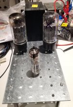
This is my idea.

What's that? Are you going to use a E/PCL85 as the first tube?
Best regards!
Those are the 12cm plates? I've used those perforated plates as sub-chassis for toroids, so I can hide the power transformer without having to suspend it on a single point on the top plate. Also, they make good back panels, with a hole cut for an IEC input.
Tricky part with something cosmetic is how to deal with the cut edges when you fix the valve bases. It is just mild steel, and without the galvanized coating I wonder how it might age.
I'm also considering using them to mount toroids on their sides on the top deck of an amplifier, with a 90 degree bend so the toroids can be fixed. What would be perfect would be a cover that goes over that assembly to make it look less DIY - some sort of metal box 12cm x 12cm x 6cm would be perfect. Does anyone know of anything that can be re-purposed?
- Home
- Amplifiers
- Tubes / Valves
- Edgar ST-70 new construction