I put it back together and measured 17.77 vac across the small transformer secondary, the little bridge diode is not putting out any voltage. IC251 and IC253 are not showing any diode voltage with a diode test? I'll wait for the little diode bridges to get here and see how it goes then? Thanks for your help, Patrick. It's appreciated.
The standby transformer output 17.77v ac is not right, there is some thing wrong with it's primary AC input circuit IC252 and Q254, in normal condition IC252 get power supply by capacitor and diode form main AC, then IC will drive Q254 to turn on the AC supply to small transformer.
Your case seems the capacitor and diode power supply form main AC for the IC252 and Q254 fail.
Please check the voltage of the zener diode D255 in main AC board.
"Careful! There is danger live AC inside, you better solder extra wires to the diode and connect it to DMM for testing.
Attachments

Thanks for the info Patrick, I've always wanted to know how these amplifiers turn on! I will check that out in the morning and let you know what's happening? It's getting late now, I better get some sleep.

I found that the diode bridge had a broken pin from when I took it out to test it. I soldered it back and now have S10 again. I replaced the failed C254 supply cap and checked the voltage of Zener diode D255 it reads 2.5vDC to ground on each end and 90Vac on each end to ground. It reads 1.4vDC across and it jumps all over the place on AC-voltage. I was going to replace it but I don't have a 10v Zener and the local electronics shop has run out of them too? So I'll have to wait a few days to get one. The output from the small transformer is in mv and jumping all over the place? Oh, and C258 checked out Ok!
Last edited:
It seem the zener diode should output 10v dc to the IC circuit, cap c258 also belong to the supply cap, pls check it
Last edited:
I found that the diode bridge had a broken pin from when I took it out to test it. I soldered it back and now have S10 again. I replaced the failed C254 supply cap and checked the voltage of Zener diode D255 it reads 2.5vDC to ground on each end and 90Vac on each end to ground. It reads 1.4vDC across and it jumps all over the place on AC-voltage. I was going to replace it but I don't have a 10v Zener and the local electronics shop has run out of them too? So I'll have to wait a few days to get one. The output from the small transformer is in mv and jumping all over the place?
the 10v zener maybe good, you can take it out test it with other power source, maybe the other supply cap c258 fail, both caps work together to form power supply.
It seem the zener diode should output 10v dc to the IC circuit, cap c258 also belong to the supply cap, pls check it
I just checked Capacitor C258 it reads Ok at 46.9 nanofarads. I will take the 10v Zener out and check it on another power supply and report back on the result?
I don't like this kind of standby power supply, there is already a small transformer for the standby power source and it no need to make a complicated AC on/off control for the small transformer anymore.
If you want, we can do an experiment to bypass the AC supply control.
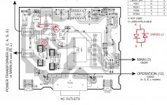
First "disconnect the cable connected to the power amp board", remove the jumper wire J261 on the main AC board and solder a diode circuit between point A and B(bypass AC supply control), and test the small transformer AC ouput and the S10 DC output is correct or not.
First "disconnect the cable connected to the power amp board", remove the jumper wire J261 on the main AC board and solder a diode circuit between point A and B(bypass AC supply control), and test the small transformer AC ouput and the S10 DC output is correct or not.
Attachments
Yes, it's a bit of a pain trying to work this one out? I tried the Zener with a 100ohm resistor, I put 13.7 volts through it and got 13.5v out? Ha! Ha! Oh well, I'll just have to wait for another 10v Zener in the post and get back when I've installed it with the results? I found a W04 1.2A 400v mini diode bridge in my junk box so I might install that as well seeing as the original is damaged. Oh, I didnt see your latest post? Can I do that without the Zener?
Yes, it's a bit of a pain trying to work this one out? I tried the Zener with a 100ohm resistor, I put 13.7 volts through it and got 13.5v out? Ha! Ha! Oh well, I'll just have to wait for another 10v Zener in the post and get back when I've installed it with the results? I found a W04 1.2A 400v mini diode bridge in my junk box so I might install that as well seeing as the original is damaged. Oh, I didnt see your latest post? Can I do that without the Zener?
Yes, you can do the bypass test without the 10V zener diode.
You can use your bridge diode and connect the + and - together and connect the bridge both ac side to the A and B points, it works same as my two diodes circuit.
Last edited:
So I should cut Jumper 261 on one end and solder the diodes to the ''A'' end and the other end to the Fuse? I cant post diagrams or photos my computer is playing up!
So I should cut Jumper 261 on one end and solder the diodes to the ''A'' end and the other end to the Fuse? I cant post diagrams or photos my computer is playing up!
Yes, you better remove the jumper and solder the diodes to the ''A'' end and the other end to the Fuse, please check the diagram.
Well that sounds easy! Ill get onto it and let you know how it went Patrick and thanks again for helping me with this.
There is no S10 and there is now 42vDC output on the little transformer. Oh! Hang on I connected to J251 instead of J261? Ill try that sorry about that chief. lol
Last edited:
There is no S10 and there is now 42vDC output on the little transformer. Oh! Hang on I connected to J251 instead of J261? Ill try that sorry about that chief. lol
Be careful, please do not make further damage to any circuit. 😱
Be careful, please do not make further damage to any circuit. 😱
I connected it up properly when I plugged it in I heard a fairly loud pop from the bottom of the board, there was no smoke but I can't find any damage except that the little transformer isn't putting out any voltage DC or AC? I measured the ohms across one end it was 29 ohms and the other was 3.200k ohms and that was what it measured previously from memory? The transistors and diodes seem to be alright? I don't know about the Mosfet though? Aha! I just found Q251 was what blew lucky I have a few of those.
- Home
- Amplifiers
- Solid State
- Yamaha RX-497 No main power?