Hi guys,
A while back I picked up a Symaudio P-200 Mk II pre-amp that needed repairs. With all the free time I have available I decided to try to salvage it. As you can see the power supply wiring was stripped. I jimmied power into the pre-amp and apart from a few problems it seems to be working fine.
(Maybe more to come later???)
I would like advice and or opinions as to how to make proper connections to the power supply. I suppose I could just attache the power cord to the 2 black wires of the Toroid (thru the fuse) and be done with it.
Voltage in is 120Vac & out is +20Vac & -20Vac.
From the picture:
the yellow & orange wires go to the bridge rectifier on the PC board.
one black wire goes to one end of fuse
one end of the power chord would go to the other black wire from the Toroid & the other one to the fuse.
on the side of the case to the right of the toroid is a ground lug with no wires.
I'm presuming that the power chord (which was not included) had only 2 wires, i.e., no ground wire.
So the question is: How best to wire this pre-amp. should I use safety caps, what connections should be made to the ground lug, etc., etc.
Any and all opinions/advice will be greatly appreciated.
Thanks
Fred P.
Attachments
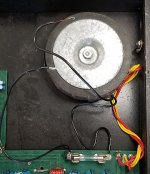
I would check continuity on the two black wires from the toroidal - they should be the primary winding and have continuity from black-to-black.
If so, there should have been a three-prong cord, with the Live (black) going through the fuse (left most black wire in your picture) and the neutral (white) going to the free hanging black wire (middle black wire in your picture) and the ground going to the grounding lug attached to the side of the case.
I would certainly use a DBT (dim bulb tester) and possibly a lower rated fuse when you first power this up, because it is high voltage and incorrect wiring will short out a lot of stuff (potentially).
Look at the image below - pic is a little more complicated because of the power switch and fuse. Follow the Brown and Orange (Live), Blue (Neutral) and the Green/Yellow (Ground) and you will see how I am describing the connections.
Attachments

Thanks bullittstang
What threw me was the ground lug. Three wire power cord it is.
I thought maybe it would be more complicated than that.
As they say, a picture is worth a thousand words.
I wonder if a safety capacitor of 0.01 mF is necessary?
Thanks again.
Fred P.
What threw me was the ground lug. Three wire power cord it is.
I thought maybe it would be more complicated than that.
As they say, a picture is worth a thousand words.
I wonder if a safety capacitor of 0.01 mF is necessary?
Thanks again.
Fred P.
Shouldn’t need for that size of toroidal, but after it’s working, if you get some buzz you could always add and see if it helps
What do you mean ("safety cap 10 uF")?I wonder if a safety capacitor of 0.01 mF is necessary?.
It think he is asking if he should put a small value cap across the live and neutral to protect from surge/spark.
What do you mean ("safety cap 10 uF")?
Firstly the value is 0.01mF and as bullittstang stated it is connected across the live & neutral wires on the primary side. This significantly reduces the RF emissions external to the enclosure.
What is different (strange?) in this design - the reason for the post - is that the power switch turns the unit on/off after the transformer. Usually or normally from what I've seen is that the power is cut/enabled before the transformer. But it seems to work. Live & learn.
Thanks for the replies.
Fred P.
I think you mean "mkF" or "uF", because 1 mF is 1000 mkF.
Right you are. uF it is.
My apologies.
Fred P.
- Home
- Design & Build
- Construction Tips
- Power Supply Connections