Hello,
I am sorry if this has been covered in the forum. I tried to search for an answer to my predicament but couldn't find an answer.
I have a rather strange issues concerning half-wave rectifiers. I have two large 575A rectifiers (5v 10A filaments each) I would like to use. I also have two 0-10v 10A (pri. 230v) transformers.
I can wire the primaries in series and obtain 5v on the secondary windings, but then - and here comes my question - can I wire each separate transformer to each full wave rectifier? Is there a preferred method to connect the choke to start filtering?
I guess what I am asking is whether I can power each half-wave rectifier independently and if there is a way to obtain filtered DC from such an arrangement. Plate voltage will come from a hybrid configuration with two diodes and the two half wave rectifiers.
I know it's a weird arrangement but I really don't want to get a new transformer made and would be really happy if I could use what I've got!
Extra scenario
Ironic as it sounds I also have two 1.25-0-1.25 transformers rated 50VA each. They were designed for 866A tubes apparently.
If connected in series, the secondary wingdings should give me 2.5-1.25-0-1.25-2.5 voltage points (primary windings would be in parallel of course).
Only problem is that each transformer is rated 11A and effectively I would be drawing twice the recommended current from each 2.5v lead. I don't believe this is a safe approach.
Important detail: each set of transformers is made of identical transformers.
I trust that the collective wisdom of the forum will come to my rescue 🙂
Like the rest of my country I am under lockdown due to COVID so having something to concentrate on is a blessing right now.
Thank you
Last edited:
Why don't you try to do away with the use of a tube rectifier and use high voltage diodes instead? There are tube amplifiers which have such an arrangement.
I really really really want to know what you think you're doing with these ginormous mercury vacuum rectifiers? They're designed to provide no less than 7,500 watts each at 5,000 volts.
Holy Cow!
OK, you want a light show, then. Fair enough … but know too that the envelope material is designed to let UV mostly pass thru. This keeps the glass envelope from heating too much during 1,500 mA average current flow. But you're running risks of getting corneal burns as well as cataracts from the naked bulbs. These were meant to be used behind opaque equipment panels!
Dunno, Alex… I think if you're barking up this tree, whether or not you have the exact amperage to drive the filaments … is kind of a moot point. Decidedly moot.
(You might want to put a low value resistor in series with the filaments so as to drop total amps down to 9 or so. They'll still light up plenty bright. Moreover, the mercury will still 'strike' when you need it to. )
⋅-⋅-⋅ Just saying, ⋅-⋅-⋅
⋅-=≡ GoatGuy ✓ ≡=-⋅
Thanks for the advice! I've used xenon and mercury rectifiers in the past and have never had issues. As for UVA, I've successfully used lexan sheets in the past as a form of protection. Equipment is never stared at, always in my direct control (I don't have kids, pets, etc.).
I understand that it's terribly inefficient but most tube projects are. My DIY 307A, mercury-rectified, gas-stabilized, mini amp outputs around 15W cumulative and costs 10 times what I would have had to pay to get the same wattage from a decent SS device. It's beautiful and I had a great time building it. My 833A seet me back 10 times more... 🙂
As for the question: I have settled for a primary in series/secondaries in parallel approach. As the secondaries are common, I should be able to extract the semi-rectified sine from either "leg" of the 0-5v wiring. Please let me know if this arrangement is flawed.
Thank you!
I have two large 575A rectifiers (5v 10A filaments each) I would like to use. I also have two 0-10v 10A (pri. 230v) transformers.
It seems suited to a industrial solder machine, for audio there is other rectifiers more adequate.
It seems suited to a industrial solder machine, for audio there is other rectifiers more adequate.
I can't see any issues with using the two transformers in series for the heater supplies. As the secondaries are completely isolated you can address any issues with absolute heater voltage.
Not sure what the idea is behind this project.
Get ooooh!!!´s aaaaah´s WOW!!!!´s?
It certainly does not meet any practical need.
Get ooooh!!!´s aaaaah´s WOW!!!!´s?
It certainly does not meet any practical need.
Hello,
I am sorry if this has been covered in the forum. I tried to search for an answer to my predicament but couldn't find an answer.
I have a rather strange issues concerning half-wave rectifiers. I have two large 575A rectifiers (5v 10A filaments each) I would like to use. I also have two 0-10v 10A (pri. 230v) transformers.
I can wire the primaries in series and obtain 5v on the secondary windings, but then - and here comes my question - can I wire each separate transformer to each full wave rectifier? Is there a preferred method to connect the choke to start filtering?
I guess what I am asking is whether I can power each half-wave rectifier independently and if there is a way to obtain filtered DC from such an arrangement. Plate voltage will come from a hybrid configuration with two diodes and the two half wave rectifiers.
I know it's a weird arrangement but I really don't want to get a new transformer made and would be really happy if I could use what I've got!
No problem, the cct you propose will work OK. The filter cct needs to be choke input (gas rectifiers), a swinging choke would be a good choice in order to reduce its size & weight. The output needs to be continually loaded while the HV is on.
If you see a significant power frequency (not rectified freq) component in the DC, exchanging the heater leads on one of the rectifiers might resolve that problem.
Around 1960 I built a 4.5KV, One Amp regulated PS, it used a full bridge of Amperex 7136 Hg rectifiers. The PT was by Hammond, more than a cubic foot of copper & iron. Very dangerous, luckily I had built in a fail safe discharge system. It saved my *** on one occasion.😱
Attachments
What do you plan to power with those 575A's? Those were used for many years in medium power transmitters...both AM and FM and TV...I worked on transmitters in the 1 kw range which ran off 230 v single phase, had a 7 kv 1 amp plate transformer, two 575A's full wave center tap...choke input filter..that furnished around 3200 volts for the RF final and modulator, typically four 4-400A..two for RF, two modulator...old Raytheon transmitter used 575A rectifiers to provide 2500 volts for four 833A...two RF and two modulator....FM transmitter used six of them (full wave three phase supply) to provide around 6200 volts for a 4CX5000A RF final... The old RCA 50 kw AM rigs used 857B's in the HV supply...The 575A was often substituted in other transmitters where excessive arcbacks occurred with the 872A.
You are dealing with some serious voltage and power when using a 575A. I assume you are using single phase power...the filament transformer should provide 5 v 20 amp (for single phase full wave center tap configuration) and be insulated for 10 kv dc...the PIV of the 575A is around 15 kv, The 575A can easily deliver one ampere continously...Be aware that tube requires a minimum 2 minute preheat prior to applying plate voltage. Arcbacks at high voltage are nasty. Carelessness can kill. Be careful handling the mercury rectifiers...you have a problem if you break one...keep some powdered sulfur around...
Last but not least... I expect that 10 v 10 amp transformer you has INADEQUATE insulation for use with 575A's. Be certain...otherwise a secondary arc due to excessive voltage will ruin the transformer....
Last edited:
... two large 575A rectifiers (5v 10A filaments each) I would like to use. I also have two 0-10v 10A transformers....
Don't think so much. Do the obvious. Attached.
This will "add 5V AC" to the rectified output. If you are going for LARGE DC voltage, 5V of AC is nothing.
Attachments
PRR - thanks for the diagram. My question is whether that arrangement is safe current-wise. Each 575A draws 10A nominal so effectively I would have 20A flowing through your filament transformer rated at 10V 10A. In terms of voltage it makes a lot of sense, but what about current rating of the transformer winding?
I attach here some very crude schematics to illustrate a question I have with respect to eliminating the superimposed 5v AC.
I did not have a symbol for a diode, hence the use of a dummy triode. Please ignore grid connection as it's not supposed to be there!
First image tries to tap into the filament windings of opposite polarity
1 — ImgBB
Second image is a fully parallel arrangement. This would without a doubt superimpose a 5v ripple on the DC output, correct?
2 — ImgBB
Thanks!
Last edited:
2-ImgBB is the better choice, paralleling the transformer secondaries forces the voltages in the secondaries to be equal, 1-ImgBB does not. There will be a small circulating current set up in the transformer secondaries caused by small differences in the transformers. As long as the transformers are the same, the circulating current will not be a problem.
If you find a power frequency component in the output ripple, reverse the heater leads to one of the 575s, that should work. Your connexion is a full bridge, if all is well there should be no power frequency ripple at all.
The cap C1 is not a good idea & may cause a failure. Gas & Hg rectifiers need to have a choke input filter. If the minimum steady state load is known the choke size can be calculated.
The filter action of an LC section is 12 db less effective at the power frequency than it is at the ripple frequency of a one-phase rectifier system, whether bridge or CT (full wave diametric).🙂
> Each 575A draws 10A nominal so effectively I would have 20A flowing through your filament transformer rated at 10V 10A.
I drew the rectifier heaters in series. Doesn't that mean 10A in the whole loop?
I drew the rectifier heaters in series. Doesn't that mean 10A in the whole loop?
Careful when connecting transformer primaries in series, even the smallest current disbalance in the secondaries will change the secondary voltages dramatically. Perhaps the paralleled secondaries from 2 will work, but generally i find this a very bad idea.
Don't think so much. Do the obvious. Attached.
This will "add 5V AC" to the rectified output. If you are going for LARGE DC voltage, 5V of AC is nothing.
By far the best idea.
Careful when connecting transformer primaries in series, even the smallest current disbalance in the secondaries will change the secondary voltages dramatically. Perhaps the paralleled secondaries from 2 will work, but generally i find this a very bad idea.
Easy to measure the circulating current between the secondaries with an AC current clamp. Not everyone has a current clamp, a way out is a sampling resistor of say 0.1R connected between the secondaries while they are in parallel. Measure the AC voltage with a DMM such as a Fluke which is RMS responding.Then apply Ohms Law.
Provided these transformers are of the same production run the circulating current should be small.
A more serious problem would be differences between the heater current of the 575As. That can be fixed by paralleling a resister to one of the heaters to get a balance if the difference is large.
Each of the 575A heaters sees the other heater as its source since the transformer primaries are in series. That creates an interesting condition, especially when one heater is hotter than the other. More on this next time.

The solution is far from impossible, altho admittedly a flaky cct.😀
Still like to know how this PS will be used.🙂
Still like to know how this PS will be used.🙂
I use a pair of NL616 in a 2A3 pp amp and don't make a big deal out of it 🙂
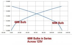
Beginning around 20 yrs ago I got serious about measuring hot vs cold resistance of some tube heaters & incandescent light bulbs. I found that most of the common receiving tubes had hot resistances in the order of 9-10 times their cold resistance. All the lower resistances were measured by the 4-terminal method to insure accuracy. At the lower temperatures the settling time often ran a minute or two.
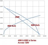
I didn't have any 575As to try, but I did some ordinary tungsten light bulbs, the kind we buy at the hardware store. Then using the Excel Spreadsheet plotted the results. Set some up so that back to back results indicated the operating point of two similar bulbs. Then two dissimilar bulbs. These examples are in the same power range as the 575A heaters so are a good indicator of how the OP can go off the rails while heaters are in series.😱
The heater of one tube is the source of the other. And Vice versa.🙂
Tubes for series string have heaters modified to result in proper tracking.
Attachments
Overkill but fun to watch anyway. Long as we don't have to buy ($$$$) those toobz or the heater transformer required. I'm thinking a 5H choke worked OK for you at the PS filter input for a PP 2A3 load.I use a pair of NL616 in a 2A3 pp amp and don't make a big deal out of it 🙂
There would be lots of RFI, both conducted & radiated. Did you have to do much to hold it down?
- Home
- Amplifiers
- Tubes / Valves
- Separate transformers for half wave rectifiers