Hello fellow DYI audio members,
This amplifier is one born out of social distancing boredom. I always wanted to take a shot at designing a class A2 single ended 300B amplifier. The attached schematics is a works in progress that I will plan build to build but I thought I would share my design as it stands and ask for some suggestions on what might be done better. A number of DYI members have offered great insights on how people might do things better on other projects and I am hoping to harvest some of there thoughts on my bordedom project amp.
Thanks Mickeystan
Attachments
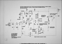
Two stages of input gain with a CCS loaded tube that has a Mu of 70 will likely be too much. The TSE uses a single stage of 5842 which has a Mu of 44 and it is about right. 5842's are getting scarce and can cost over $10 each. Good cheap tubes are the 6J4 and a triode wired 6EJ7.
The output impedance of the mosfet that's driving the 300B is a few ohms, The choke is not really needed since the mosfet will have no issues driving a 10K resistor. The mosfet follower is an asymmetrical source, it can put lots of current into the grid of the 300B thus quickly charging the Miller capacitance on a sharp transient. The resistor is the only path for current to flow out, discharging the Miller capacitance. Why slow it down with a choke?
Many modern production 300B's, and most old stuff will not like 440 volts on the plate. Make sure that your tubes can eat this much voltage before you go there. I know from years ago that the old Sovteks will run away on anything over 400 volts regardless of what their literature says.
Look at the schematic of the Tubelab TSE in post number 1 of this thread. It's a proven design that's been around for 15 years.
After a 14 year run, the TSE must DIE!
Hello there,
I would like to ask about current and power dissipation of the grid when goes positive
Most classic audio tubes including 300B have no data about grid1 limits. Is there a way to estimate these?
I would like to ask about current and power dissipation of the grid when goes positive
Most classic audio tubes including 300B have no data about grid1 limits. Is there a way to estimate these?
Last edited:
Tube Lab, Thank you for the feedback. I totally agree that the two stages of 12AT7 provide too much gain and that is why the level control at the frontend is actually a divide by two network for AC input signal. I did it this way as I have alot of 12AT7s sitting in my stash of tubes. I will play with removing the choke and also look at going to a single input stage of one of the suggested tubes. I will also spend some time reading your suggested post. Thanks again for your feedback. Mickeystan
I have alot of 12AT7s sitting in my stash
I have a BIG box full of old 12AT7's pulled from military spare equipment. That's how they wound up in the Tubelab SSE amp.
I had a bunch of 5842's back when I designed the original TSE about 17 years ago. I simply measured the characteristics of CCS loaded driver stages using every tube that I had a bunch of. The 5842 was the best with the 6J4 not far behind, but PCB 7 pin sockets were not common back then. There were a few different 9 pin pentodes that worked pretty good when wired as triodes, but the 6EJ7 is the only number I can remember right now.
The 12AT7 was never intended for audio use since it is not the most linear triode available. It's distortion is mostly second harmonic, some of which will be cancelled in a two stage amp where both stages are triodes. Try them if you have them, they might work out just fine. Another idea is to try using one driver stage using both sections of a 12AT7 wired in parallel with the total current in the 15 to 20 mA range.
ask about current and power dissipation of the grid when goes positive
The grid should only go positive on large signal transient peaks which are brief and rare in usual HiFi listening. The dissipation under these conditions is so short that the average grid dissipation is not affected. I don't think that I would want to operate and expensive 300B under conditions where the excursions into heavy positive grid are continuous for more than a few seconds. I do subject every amp I build to some serious testing and that involves plugging my guitar preamp in and blasting away for a while.....The Chinese 300B's laughed it off, and didn't sound too bad either.
Last edited:
Tube Lab, Thank you for the feedback. I totally agree that the two stages of 12AT7 provide too much gain and that is why the level control at the frontend is actually a divide by two network for AC input signal. I did it this way as I have alot of 12AT7s sitting in my stash of tubes. I will play with removing the choke and also look at going to a single input stage of one of the suggested tubes. I will also spend some time reading your suggested post. Thanks again for your feedback. Mickeystan
If you've got 12AT7s to burn, you could have a differential stage and take the output from just one side, which might cancel the copious 2nd harmonic distortion from the 12AT7 and reduce the gain to ~35 for that stage.
It's probably useful to quantify what will be gained by pushing into A2. At 400V PK and 53mA into a 5K load, it looks like you can swing up to 675V, then in A2 back down to wherever Vp=Vg, so call it 30V. That's 370V down and 275V up. The extra push into A2 doesn't seem to be worth it.
Based on the drip of grid current that's required and your hoard of 12AT7s, it's quite possible that a 12AT7 cathode follower could get you there without the fet. (TubeLab is going to hate that suggestion!)
Based on the drip of grid current that's required and your hoard of 12AT7s, it's quite possible that a 12AT7 cathode follower could get you there without the fet. (TubeLab is going to hate that suggestion!)
I ran a 5k SE transformer up to 18.5 Watts on 450V B+ once. I believe I had to bias at 90mA or so to get a symmetrical swing capability. The output device was a mosfet follower so it was able to drive almost all the way down to 0V.
The 300B can't do what the mosfet could, but you will have to increase current and probably lower B+ a bit to get to the sweet spot for symmetrical swing and pretty decent power output.
The 300B can't do what the mosfet could, but you will have to increase current and probably lower B+ a bit to get to the sweet spot for symmetrical swing and pretty decent power output.

Audiowize,
I want to push into A2 just for the fun of it and to realize as much power as I can safely push a single 300B output tube into. Of course, I will ease into the increased power progressively and see how the tube deals with it. I have built single ended 300B amps in the past and they have all been simple class A without feedback and made 8watts of output power. This time, I want to wrap feedback around it increase the flattened out power band, lower distortion and improve the dampening. This project is to fill out time and displace boredom on being stuck at home. When its done and up and running I will see how I think it compares to my other non feedback 300B amps. As for the Mosfet source follower, I have built many source followers in my life (tube and Fet). The Fet source follower is simply better at the task with much lower output impedance. Mickeystan
I want to push into A2 just for the fun of it and to realize as much power as I can safely push a single 300B output tube into. Of course, I will ease into the increased power progressively and see how the tube deals with it. I have built single ended 300B amps in the past and they have all been simple class A without feedback and made 8watts of output power. This time, I want to wrap feedback around it increase the flattened out power band, lower distortion and improve the dampening. This project is to fill out time and displace boredom on being stuck at home. When its done and up and running I will see how I think it compares to my other non feedback 300B amps. As for the Mosfet source follower, I have built many source followers in my life (tube and Fet). The Fet source follower is simply better at the task with much lower output impedance. Mickeystan
Well, if you want more power, you will need to run more idle current.
I didn't notice the gnfb loop. You have a series feed OPT that will support that much feedback?
I didn't notice the gnfb loop. You have a series feed OPT that will support that much feedback?
audiowise,
A 12AT7 as a cathode follower driving a 300B that has -90V grid bias may not be so good.
The 12AT7 maximum cathode to filament voltage is 90V.
Cutting it close?
Just that one spec makes me want to stay away from using it that way.
Ask those who have had to replace the expensive 7199 tubes in a Dyna Stereo 70.
Did any of the triode sections in the split load phase splitter ever have a very high leakage current of the cathode to filament (the circuit abused them by exceeding the max voltage spec).
Last edited:
Audiowize,
The amplifier as detailed in the posted schematic models as being able to make 17 watts rms with 1.9vpp input at 1khz. The posted idle current of 53 ma. sets the idle dissipation at 23.16 watts or about 77% of the 300b's 30 watt rated capability. As for output transformers, I have two to play with. One is a Transcendar and the other is Edcor. My guess is both will likely handle the feedback but the actual proof is in the pudding as they say. At this point I am still playing with the design. I will likely build it without the choke as Tube lab pointed out it is really not necessary if I feed the 10k load resistor of the Mosfet with the increased B-. Playing too with alternate voltage amp stages as has been suggested. In the end, I may build it with just the elimination of the choke as it models very well with the current frontend.
Mickeystan
12at7 tube ?, have a ton more linear and
too much gain 70 * 70 = 4900 when 300b 12w grid need 160v RMS = 224Vp
Mosfet deteriorate the natural sound of 300b ( EMO )
300b 4k to 4k5 load do not need NFB, again deteriorate the natural sound ( EMO )
300b has a crystalline sound, rich in details, work very clean without patch.
the old combination 6sn7 x 6sn7 always have worked very good ( 20x20 ), with CCS low mu maybe can work in A2 else double triode or cathode follower.
One could bias the heater winding at -45V.audiowise,
A 12AT7 as a cathode follower driving a 300B that has -90V grid bias may not be so good.
The 12AT7 maximum cathode to filament voltage is 90V.
Cutting it close?
audiowise,
Bias the filament at 45V? . . . OK.
The cathode swings up 90V.
The cathode swings down 90V.
Somewhere in that 180V peak to peak swing, you might exceed the 12AT7's cathode to filament's maximum voltage ability.
I do not know, but I will not try it.
I see the lowly 12AU7 has a 180V cathode to filament rating. A 12AU7 might be a good candidate for a cathode follower.
Sorry, the transconductance is only about half of the 12AT7. How about paralleling the 2 triode sections?
Or, go out an find another tube that 'does it all'.
Or change the circuit topology. MOSFET anybody? Lots of people on this forum have done that successfully (I will not do that).
Last edited:
Celsius,
12AT7 tubes have a spec'd amplification factor of 60 not 70. As I have them implemented with the CCS plate loads they are actually amplifying at 43.3. As such the total gain is not as high as you are thinking. Nonetheless, I do have more gain than I need. In contrast I have also played with doing the same topology with two gain stages of 6SN7 tubes mu spec'd at 20. With this combination, I do no have enough gain to do the feedback I am looking for. I too have experience with 300B amplifiers running with no feedback and making only 8 watts of output. My pair perform well for what they are but in all honesty, I will not make a bold statement that they sound much sweeter than any of my many built Push Pull amplifiers running feedback and high quality output transformers. In fact, me and my audio friends agree, it is dam hard to tell them apart. I am not interested in getting into discussions on what sounds best. I am more interested in doing something different as I have a lot of time on my hands now sitting here at home due to the ugly Corona Virus mess going on. Wishing you and all the other DYI members good health as we all work though the current situation.
Mickeystan
An unbypassed cathode normally causes gain to be less than u.
Post # 1 gain state tubes are not bypassed.
The gain is also dependent on the plate load. The plate load is the CCS's impedance and the next stage's grid resistor (they are in parallel for signals, but not DC).
A 12AT7 gain of 43.3 seems reasonable for many typical circuits.
Post # 1 gain state tubes are not bypassed.
The gain is also dependent on the plate load. The plate load is the CCS's impedance and the next stage's grid resistor (they are in parallel for signals, but not DC).
A 12AT7 gain of 43.3 seems reasonable for many typical circuits.
- Home
- Amplifiers
- Tubes / Valves
- 300B SE A2 amplifier