Hi all!
A while ago I got cheap DAC from China, upgraded it with better capacitors and power supply and got great sound, compared to built-in sound card. The main difference - I got rid of any noises, that caused by videocard or mouse while heavy usage of PC.
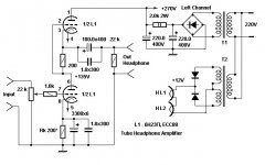
Then guys, who gave advises on DAC, recommended me to try build something with tubes, especially cheap soviet (russian) tubes, widely available here in Ukraine. I have lot of experience with microcontrollers, but not with analog electronics, so started searching something easy to get with components I have. That time I found popular DIY OTL headphones amp with simple schematic and only two 6N23P tubes for stereo (first attachment).
After few tests and versions of this amp, I modified its schematic, added vacuum indicator tube, got rid of noise at all and now it looks like perfectly stable.
My final version schematic attached here too.
Just one thing still worry me. After 6N23P I purchased two Tesla E88CC Military grade. They sound much better, but they died after 3 month of use.
I thought issue was with my mains - voltage here vary from 180 to 230 VAC, but I using UPS and it upscales voltage to 205-248 VAC. As result heater voltage without stabilization was 5.9 to 7.1 VAC. (Now I using 16-steps voltage stabilizer, but only for last 2 month).
To solve that I decided to added rectifier and LT1083 for stabilization and got stable 6.3VDC now.
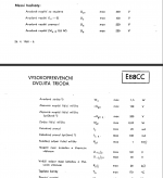
All works nice, but my paranoid brain still keeping one thing - heater to cathode voltage. Schematic is based on SRPP and for bottom stage Ufk equal to 2V, then for top stage Ufk = 114V. For Tesla E88CC tubes this value very close to its maximum (120V), so I got Tungsram E88CC tubes with bigger Ufk = 150V.
I'm very beginner with tube amps and spent tons of time searching for something that could give me idea how to deal with this dilemma, but still have no success.
Some materials, that points me to heater problems and heater-cathode voltage in SRPP:
1. Elevated DC heater supply
2. http://deewm.com/Webcache/The_Valve_Wizard/Heater_Filament_Supplies/Heater_Filament_Supplies.html
3. https://www.diyaudio.com/forums/tubes-valves/346343-cathode-follower-heater-cathode-voltage.html
Maybe you guys can help me? Do I need to elevate heater voltage here? Or disconnect heater ground and leave it floating? But with floating heater I getting noticeable hum with 32Ohm headphones.
Thank you very much!
A while ago I got cheap DAC from China, upgraded it with better capacitors and power supply and got great sound, compared to built-in sound card. The main difference - I got rid of any noises, that caused by videocard or mouse while heavy usage of PC.
Then guys, who gave advises on DAC, recommended me to try build something with tubes, especially cheap soviet (russian) tubes, widely available here in Ukraine. I have lot of experience with microcontrollers, but not with analog electronics, so started searching something easy to get with components I have. That time I found popular DIY OTL headphones amp with simple schematic and only two 6N23P tubes for stereo (first attachment).
After few tests and versions of this amp, I modified its schematic, added vacuum indicator tube, got rid of noise at all and now it looks like perfectly stable.
My final version schematic attached here too.
Just one thing still worry me. After 6N23P I purchased two Tesla E88CC Military grade. They sound much better, but they died after 3 month of use.
I thought issue was with my mains - voltage here vary from 180 to 230 VAC, but I using UPS and it upscales voltage to 205-248 VAC. As result heater voltage without stabilization was 5.9 to 7.1 VAC. (Now I using 16-steps voltage stabilizer, but only for last 2 month).
To solve that I decided to added rectifier and LT1083 for stabilization and got stable 6.3VDC now.
All works nice, but my paranoid brain still keeping one thing - heater to cathode voltage. Schematic is based on SRPP and for bottom stage Ufk equal to 2V, then for top stage Ufk = 114V. For Tesla E88CC tubes this value very close to its maximum (120V), so I got Tungsram E88CC tubes with bigger Ufk = 150V.
I'm very beginner with tube amps and spent tons of time searching for something that could give me idea how to deal with this dilemma, but still have no success.
Some materials, that points me to heater problems and heater-cathode voltage in SRPP:
1. Elevated DC heater supply
2. http://deewm.com/Webcache/The_Valve_Wizard/Heater_Filament_Supplies/Heater_Filament_Supplies.html
3. https://www.diyaudio.com/forums/tubes-valves/346343-cathode-follower-heater-cathode-voltage.html
Maybe you guys can help me? Do I need to elevate heater voltage here? Or disconnect heater ground and leave it floating? But with floating heater I getting noticeable hum with 32Ohm headphones.
Thank you very much!
Attachments

I's suggest they you elevate filament voltage.
The very best woulf be to have the top triodes in one bottle and have a separate
filament elevatoed to 100 Volt, and use another grounded filament to the bottom triodes.
You seem already to have 2 6V windings, split them , don't care about DC use them
for top respective bottom triodes.
If that is not possible then at least elevate the common filament to middle voltage ( 60Volt?) DC with no filtercaps could be worse then AC as the diodes might inject
noise.
If you are interested in the mechanisms of heater-to-cathode failures and the relation between voltage and lifetime, try to find
Rodenhuis, Santing and Van Tol, "The life and reliability of valves", Philips Technical Review, vol. 18 (1956-1957), number 7, pages 181...216, December 1956
It is on the Internet somewhere.
If you just want your circuit to be as reliable as possible, just do as Peter wrote.
Rodenhuis, Santing and Van Tol, "The life and reliability of valves", Philips Technical Review, vol. 18 (1956-1957), number 7, pages 181...216, December 1956
It is on the Internet somewhere.
If you just want your circuit to be as reliable as possible, just do as Peter wrote.
I want circuit to be as reliable as possible just because it's getting harder to find tubes in good conditions here, but information always useful.
Think I will try to split top and bottom sides, and have bottom side heater powered using DC from 6.3 VAC transformer windings and schottky diodes in rectifier, while top side will be powered using another 6.3 VAC windings and elevation up to 100V.
Hope there will be no noise in result.
Thank you for ideas and information
The article Marcel suggested can be found here: http://nvhrbiblio.nl/biblio/tijdschrift/Philips%20Technical%20Review/Philips-Technical-Review-1956.pdf
You don't need to rectify filament as this is a high level signal. KeepingI want circuit to be as reliable as possible just because it's getting harder to find tubes in good conditions here, but information always useful.
Think I will try to split top and bottom sides, and have bottom side heater powered using DC from 6.3 VAC transformer windings and schottky diodes in rectifier, while top side will be powered using another 6.3 VAC windings and elevation up to 100V.
Hope there will be no noise in result.
Thank you for ideas and information
AC will also keep filament voltage more stable and the amp less complicated.
EL504, thanks.
petertub, I will try both ways, but rectifier and linear regulator already have ideal location inside aluminum case I using. Also today I got that using Schottky diodes with low drop provides stable 6.3VDC from 6.3VAC winding, with up to 0.9A on 1.9A winding. Quite enough for bottom stage tube and indicator tube 🙂
petertub, I will try both ways, but rectifier and linear regulator already have ideal location inside aluminum case I using. Also today I got that using Schottky diodes with low drop provides stable 6.3VDC from 6.3VAC winding, with up to 0.9A on 1.9A winding. Quite enough for bottom stage tube and indicator tube 🙂
- Home
- Amplifiers
- Tubes / Valves
- Heater-Cathode Voltage in OTL Headphones Amplifier