One OLED will not work as you will miss part of the UI and it will be difficult to use the preamp.
If one display is needed then the VFD is the solution.
If one display is needed then the VFD is the solution.
Thanks for the reply. If you don't mind, can you share the UI with 1 vs 2 display's. What are the differences.One OLED will not work as you will miss part of the UI and it will be difficult to use the preamp.
If one display is needed then the VFD is the solution.
No major differences. Oled just bring more details with the increased display area.
By the way if some are interested to use the vfd then I'll have to mount one and make sure that the UI is bug free. It all works, I am sure about this but I coded the MCU FW for the vfd just imagining how it will looks like on the display.
So there might be minor UI issues but no problem I can check this if some mount the vfd (to my knowledge no one did so far on HCFR GB, all went for OLED)
So let me know if vfd is your choice.
Last edited:
Hi Alex,
I see we have 4 inputs for each channel. Can we configure one of them as HT (home theater) bypass?
I see we have 4 inputs for each channel. Can we configure one of them as HT (home theater) bypass?
Thanks Alex. It is great news for me to seamlessly switch between two pramp.
I would like to ask one more question about the input output PCB. According to AES48 standard, the Pin 1 of XLR socket should connect to chassis via shortest possible route, and not to the audio circuit GND. Does the input/output PCB follows the AES48 rule?
I would like to ask one more question about the input output PCB. According to AES48 standard, the Pin 1 of XLR socket should connect to chassis via shortest possible route, and not to the audio circuit GND. Does the input/output PCB follows the AES48 rule?
Alex,
One thing that didn't seem to be addressed in the HCFR thread was how to connect the encoder (Bourns). It appears from your pics of yours in the first few posts that you had used a proto board for connect this. I'd started doing a PCB in Eagle for this. From your pic, it appeared that you wired an LED directly from the uC board connector (including ground). I assume the LED is for volume knob backlighting. Normally, when I have backlighted a knob, it is with 3 LEDs (or 4). Does the uC board supply enough to do that? Also, I assume you need to account for the addition of a resistor for the LED(s)?
I ordered one of Bourn's cables just as a temporary measure until I decide the best approach for the final. This stuff isn't covered in the BOMs.
One other thing: on your boards, the part pad layout for the 0805 resistors seems to be pretty generous (a good thing). I have found that 1210 resistors actually fit the spacing you have provided. I had a bunch of 10K 1210 resistors and decided to use these around the switches. I don't think it will be a problem. Not an actual question I guess...
And thank you again for such a complex but well thought out project!
Chris
Last edited:
Hello Chris,
Ok here are the details.
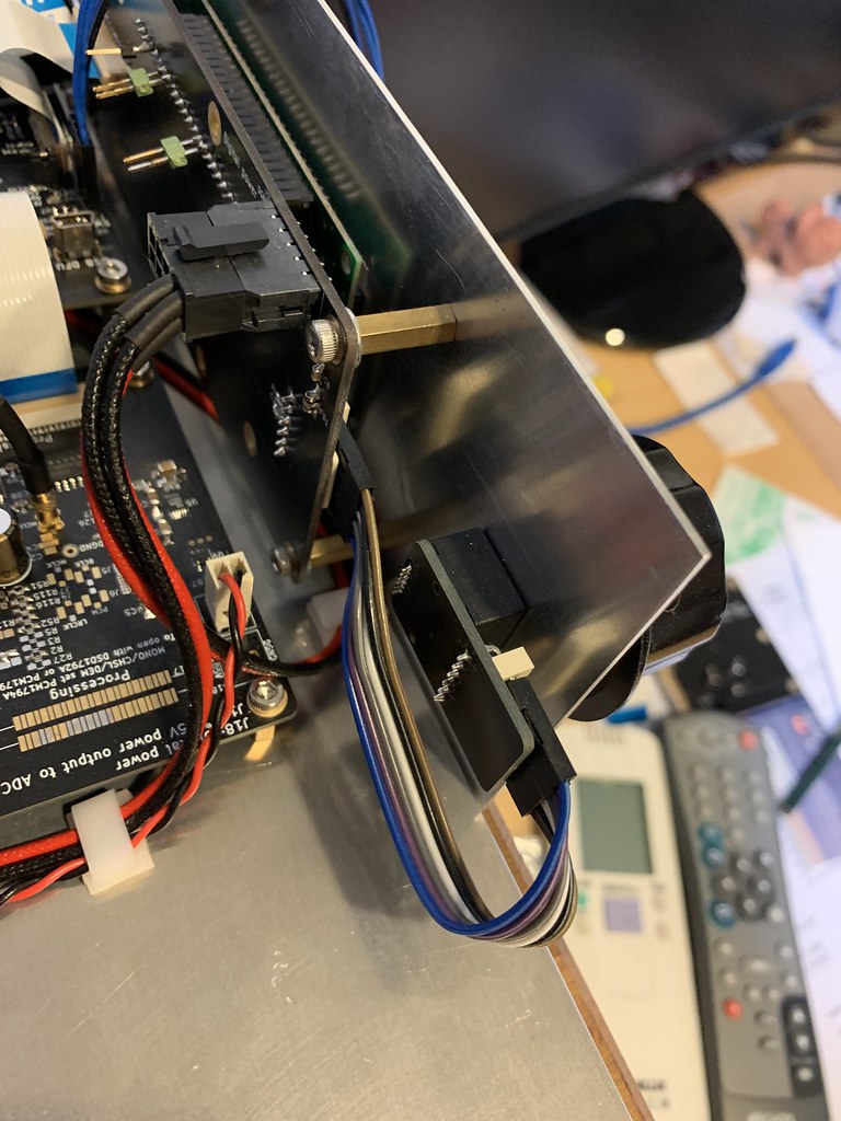
The connector / flat cable ordered long time ago for this encoder during the UGS AI GB was not fitting well and was loose. I did not like it.
So I found this PCB you see on the photos in some local shops. It is just a 1.27 to 2.54mm direct wiring and is doing the job. Then as the PCB is quite long, I took the opportunity to wire as well the two LEDs that light the volume knob backlight. There are only two LEDs as the front panel can only accommodate two with two holes. With a different front panel it is probably possible to add more LEDs. The current drained by the LEDs should not be an issue and R18 will set the total current for all LEDs.
By the way, I am using two encoders like those as well on the new DAC I am designing and made quickly some nicer PCB to be mounted on the encoders to get 2.54mm pitch.
I can provide some PCB like this in the GB if it helps you.
Those PCB on the other hand do not have the LEDs power as I designed a new front panel board on the DAC a bit different from the UGS muse.
Then no problem for the 1210 if they mount on the PCB.
Ok here are the details.
The connector / flat cable ordered long time ago for this encoder during the UGS AI GB was not fitting well and was loose. I did not like it.
So I found this PCB you see on the photos in some local shops. It is just a 1.27 to 2.54mm direct wiring and is doing the job. Then as the PCB is quite long, I took the opportunity to wire as well the two LEDs that light the volume knob backlight. There are only two LEDs as the front panel can only accommodate two with two holes. With a different front panel it is probably possible to add more LEDs. The current drained by the LEDs should not be an issue and R18 will set the total current for all LEDs.
By the way, I am using two encoders like those as well on the new DAC I am designing and made quickly some nicer PCB to be mounted on the encoders to get 2.54mm pitch.
I can provide some PCB like this in the GB if it helps you.
Those PCB on the other hand do not have the LEDs power as I designed a new front panel board on the DAC a bit different from the UGS muse.
Then no problem for the 1210 if they mount on the PCB.
Last edited:
Update today, here are the missing persons:
Fabian85
Ozcal
So as agreed let's not wait anymore and close this part now, I will order 3 more PCB sets in case.
Next step is to check where I can ship now with everyone's address given the current limitations in Taiwan and confirm the shipping fees.
After that payment, order and shipping to all of you.
Eric could you confirm all the powers supply we exactly need please?Hi Chris and others,
The shunt PSU I made works from unregulated DC voltage inputs and provide voltage regulated outputs.
In order to set +/- 24Vdc, you need unregulated voltage around 29V-36V at its inputs.
And as to cope with the inherent power dissipation of a shunt PSU, current limitation will be set to be around 150mA per rail from BOM which is enough to power 1 channel preamp board.
Hence that means you need to plan for a transfo 24V+24V AC with at bare minimum 5VA+5VA (check transfo specs for admissible operating current per secondary and apply some margins) + of course bridge rectifier + filter.
Also do not plan use the Salas PSU with the UGS muse listed 230V transformers from the previous group buy. These are only 2.5VA+2.5VA capable so not enough for this shunt version.
As for the other version, not sure if Alex managed to obtain the Gerbers for it as it is quite dated, but its is originally the so-called "alim simple" in the french forum. Many like myself and Alex, got these PCBs from old GB.
It serves the same purpose as the Shunt version but as it is a linear version, current requirements are much less.
-- Eric
That is what i found in HCFR Forum:Rechercher - Page 2
Sorry in French...Eric you wrote on 27 Oct 2015.
"Voici:
Carte preamp:
entre +/-18v min et +/-35v max redressé ou +/-24v régulé (attention en version +/24v il faut prévoir une alim additionnelle type UGS simple non prévu dans la CG en cours)
+5v pour les relais
Carte MCU:
+6v (il est sans doute envisageable d'alimenter directement en 5v en bypassant le(s) LDO(s) 5V sur la carte - non testé)"
also that is the link for the gerber for the old UGS AI and UGS simple
alims ugs.rar - Petit Fichier
Last edited:
Shipping restrictions vary. If shipping to a specific destination is prevented, then simply hold on to the package and wait until restriction is lifted. I am fully aware of that fact that this might affect me as well and I'm fine with that.
Alex i can be a cluster for European Union countries let me know, i have time ....Update today, here are the missing persons:
Fabian85
Ozcal
So as agreed let's not wait anymore and close this part now, I will order 3 more PCB sets in case.
Next step is to check where I can ship now with everyone's address given the current limitations in Taiwan and confirm the shipping fees.
After that payment, order and shipping to all of you.
Eric could you confirm all the powers supply we exactly need please?
Well, if I understand correctly your question, you end-up having 3 system level options.
a) without additional PSU - in this case the UGS+buffer modules are powered directly at +/-16V from the low noise regulators located on the preamp boards (same power rails as the muse device).
b) thanks to an additional PSU if you wish to power the UGS+buffer modules at +/- 24V and for this you have 2 options (3 if you wish to use a 3rd party board):
>> b-1) using the old legacy "simple" discrete linear supply from Flat - old but yet very low noise.
>> b-2) using the new shunt Salas regulator.
For options a and b-1, the existing info within the BOM applies.
For option b-2, it is same as b-1 except you need transformers with higher VA characteristics.
Last edited:
- Home
- Amplifiers
- Pass Labs
- UGS-muse preamp GB