sorry that I ask too much here I was reading through most of this design H900 other members experience building this H900 and I don't have doubt in my mind if I decide to build it I will not regret it I think I over think this way too much I'm just gonna follow the schematic and original layout design and try out if I fail I don't mind at least I'm trying and I'm not gonna post here any more till I got something done ok vargasmongo3435 sign out till I got something that is done not typed 😉
Attachments

hey guys for those who are using Sprint Layout 6 let me know if you need the Apex H900 file I just re-draw it for my collection if some one need it let me know 🙂
Hi, I need it if you can share it.
Thanks.
the files are on post number #3903Hi, I need it if you can share it.
Thanks.
please is for diy build and enjoy 🙂 I sometimes tweak the files and this is the last thing I did to it and is here
Attachments
hello to all the forum members..
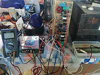
I did this project, but I also have a small problem, the amplifier works perfectly but only on the small RAIL voltage 55v , output only 33v RMS 8 ohm
I measured each piece separately, and it's ok
where is the problem thank you
i m New, thx for understanding
I did this project, but I also have a small problem, the amplifier works perfectly but only on the small RAIL voltage 55v , output only 33v RMS 8 ohm
I measured each piece separately, and it's ok
where is the problem thank you
i m New, thx for understanding
hello to all the forum members..
I did this project, but I also have a small problem, the amplifier works perfectly but only on the small RAIL voltage 55v , output only 33v RMS 8 ohm
I measured each piece separately, and it's ok
where is the problem thank you
i m New, thx for understanding
please ?? where is the problem .. is in the rail mosfet high voltaje ????
The Mosfets, for some reason are not turning on. There are many things that could be responsible for this, even if they seem highly unlikely. Try testing the commutator circuits individually, with a DC voltage instead of the audio signal. Makes fault finding a bit easier.
The Mosfets, for some reason are not turning on. There are many things that could be responsible for this, even if they seem highly unlikely. Try testing the commutator circuits individually, with a DC voltage instead of the audio signal. Makes fault finding a bit easier.
thx its a new start .. respect
I'll come back with details once again thanks
apex td1800 test..dummy load 250w 6ohms immerse at salt water,,,
YouTube
YouTube
An externally hosted image should be here but it was not working when we last tested it.
YouTube
YouTube
Hi guys, newbie here. I am currently looking at building the H900 however its extremely difficult to find the NSL32 in South Africa, is there an alternate that can be used ?
Have you checked if the output stage sliding voltage tracks the signal good enough? Do you get any visible distortion on the scope when testing with sine tones?
If anyone wants to play with ltspice...
The circuit should work fine except that the simulation is a bit slow. The models with .asy files have to be installed by hand as these cannot be loaded with an .inc statement afaik.
I've tried simulating a minimal version of the circuit and it does not look that promising. The down-converters do not track the signal very well and sine testing at 20kHz and full power may damage the output transistors as the blocking output transistors will get the sum of both rail voltages across them. Distortion performance is not very good either.
However it remains open if that is just related to the simulation or if a real amplifier will behave exactly in the same way.
Attachments
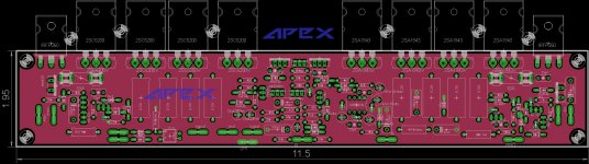
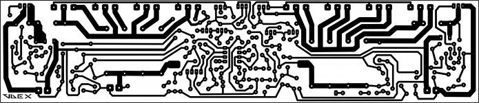
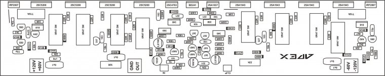
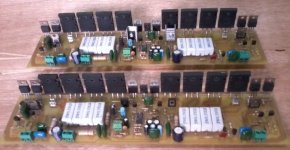
it is apex design , but i redesigned the pcb to suit my needs😀.
check the below files and also go to post #1680 , #1996 , #2578 , #1346 and #3597 #3598
900W H-class PA Amp with Limiter
900W H-class PA Amp with Limiter
900W H-class PA Amp with Limiter
900W H-class PA Amp with Limiter
900W H-class PA Amp with Limiter
check the below files and also go to post #1680 , #1996 , #2578 , #1346 and #3597 #3598
900W H-class PA Amp with Limiter
900W H-class PA Amp with Limiter
900W H-class PA Amp with Limiter
900W H-class PA Amp with Limiter
900W H-class PA Amp with Limiter
Attachments
-
 900W H-class PA Amp with Limiter pg360 Bottom 265,5 x 57.jpg816.2 KB · Views: 468
 -
 900W H-class PA Amp with Limiter pg133 APEX Hclass PowerMON.jpg274.5 KB · Views: 535
 -
 900W H-class PA Amp with Limiter pg200 APEXH900SCH1.jpg85.4 KB · Views: 585
 -
 900W H-class PA Amp with Limiter pg200 H9.jpg72.6 KB · Views: 932
 -
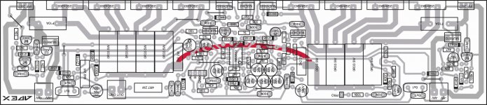 900W H-class PA Amp with Limiter pg258 Class H top layout.jpg647.9 KB · Views: 996
 -
 900W H-class PA Amp with Limiter pg135 APEX H900 correct.jpg610.3 KB · Views: 1,061
 -
gtG apex h 900 smd discreet lp.zip407.7 KB · Views: 348
Have you checked if the output stage sliding voltage tracks the signal good enough? Do you get any visible distortion on the scope when testing with sine tones?
class TD buck test - YouTube
HiHi guys, newbie here. I am currently looking at building the H900 however its extremely difficult to find the NSL32 in South Africa, is there an alternate that can be used ?
It can be replaced by some models made in China, such as cxd-32 cxd-32sr2 cxd-32r3
Does anyone know who design this pcb ???
Pak boleh minta layout ax20 clas h
- Home
- Amplifiers
- Solid State
- 900W H-class PA Amp with Limiter