Hi Everyone,
Since I am stuck at home in lockdown, I might as well repair amplifiers 😀.
I am currently trying to repair a Nad C315BEE. It stays in protection mode.
I replaced some dying capacitors in it as a first step. Most of the capacitors located near the heatsinks were obviously dead.
The thing is... it still stays in protection.
I cannot find anything wrong with this amplifier : power supply rails are all working, no shorted transistor...
The only thing I can see: it does not amplify anything.
I use a smartphone with a signal generator application.
560mVpp coming out of the phone, 400mVpp going into the power amplifier (and coming out of the preamplifier), 180 mVpp coming out of the power amp with a heavy distortion.
Both channels behave in the same way.
I am kind of puzzled right now...
I have seen another thread where the owner had to replace the protection circuit, but I assume that even if my protection circuit is bad, the rest should be working?
Any thoughts ?
Attachments
did you check the voltage on the Q218 collector?
did you check the voltage on the power output transistors ?
did you check the main voltage +5v +/-17v +/-45v ?
did you check the voltage on the power output transistors ?
did you check the main voltage +5v +/-17v +/-45v ?
Hi,
At Q218's collector, I see +45V.
All supply rails are OK, here are my measurements :
+4.99V
+16V
-16V
+47V
-45V
Regarding the power transistors, I see for Q215 and Q115 : +45V at Base and Emitter.
For Q217 and Q117: -45V at base and emitter.
On L12 and L22, I see 0V.
Thanks! 🙂
At Q218's collector, I see +45V.
All supply rails are OK, here are my measurements :
+4.99V
+16V
-16V
+47V
-45V
Regarding the power transistors, I see for Q215 and Q115 : +45V at Base and Emitter.
For Q217 and Q117: -45V at base and emitter.
On L12 and L22, I see 0V.
Thanks! 🙂
pls check relay RL301 coil pin voltage
Voltage drop across the coil is 0V, the relay stays open.
There is small flick at power on, so I would assume that the relay works as it should.
please check the resistor connected to the relay and the protection ic pin6 voltage which connect to the relay resistor
Measure Q501 collector voltage to GND, expect about 5Vdc, ie, not conducting otherwise test Q501 for a c-e near short.
Voltage drop across the coil is 0V, the relay stays open.
in order to check the protection IC ok or not, please check the resistor and the voltages, also all the IC pins voltage as well.
Attachments
in order to check the protection IC ok or not, please check the resistor and the voltages, also all the IC pins voltage as well.
The resistor is OK.
The voltages I have are (all in DC):
1: 0V
2: 0V
3: -0.7V
4: -18.3V
5: 0V
6: 31.5V
7: 0.43V
8: 4.9V
The protection IC is not a UPC1237, it is a discrete replacement. My readings look consistent with the ones in this thread:
NAD C315BEE - Help with repair!
What puzzles me is that even if the protection IC is bad, I should have normal operation of the amplifier before the relay? If I am correct, the protection IC only drives the relay to connect or disconnect the speakers.
Right now, the fact that I do not have any gain in the amp would point to other failures?
Measure Q501 collector voltage to GND, expect about 5Vdc, ie, not conducting otherwise test Q501 for a c-e near short.
I have 0V there, but the transistor looks OK. I replaced it just in case as I had another one lying around. To me, this one just controls the LED display for the µControler after.
Ok, your amp look like MCU under the remote mute condition and the amp inputs muted by Q105/205.
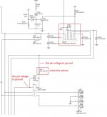
You can remove the control resistors R193/293 to release the mute control and you will get the amp working without the protection relay.
You can remove the control resistors R193/293 to release the mute control and you will get the amp working without the protection relay.
According to your protection IC voltage, the IC maybe malfunction and the pin6 gives a high signal(protection) to MCU, so that MCU mute the amp signals.
To test it, first remove the protection IC and then short the PCB pin6 to ground to make a low signal(normal) to MCU, so that try to see if the amp can work as normal.
To test it, first remove the protection IC and then short the PCB pin6 to ground to make a low signal(normal) to MCU, so that try to see if the amp can work as normal.
Ok, your amp look like MCU under the remote mute condition and the amp inputs muted by Q105/205.
You can remove the control resistors R193/293 to release the mute control and you will get the amp working without the protection relay.
You are absolutely right, I removed the two resistors and the output before the relay is perfectly normal with a nice 25Vpp at max volume and roughly 0Vdc.
The amp is still in protection. I guess I can now replace the protection IC?
Thanks for your help 🙂
The amp is still in protection. I guess I can now replace the protection IC?
To test the MCU function, first remove the protection IC and then short the PCB pin6 to ground to make a low signal(normal) to MCU, so that try to see if the amp can work as normal.
To test the MCU function, first remove the protection IC and then short the PCB pin6 to ground to make a low signal(normal) to MCU, so that try to see if the amp can work as normal.
Just did it: the amp works perfectly (albeit, without soft start).
- Home
- Amplifiers
- Solid State
- Nad C315BEE repair