Search for aa14 which is based on ax 14 I think.
I don't know much details, so may be run a sim and see for yourself.
I don't know much details, so may be run a sim and see for yourself.
Thanks Prasi for the quick reply 🙂
Found the AA14 layout design done by you. Is that the final working version?
https://www.diyaudio.com/forums/sol...imate-fidelity-amplifier-946.html#post5039388
Regards,
Sha
Found the AA14 layout design done by you. Is that the final working version?
https://www.diyaudio.com/forums/sol...imate-fidelity-amplifier-946.html#post5039388
Regards,
Sha
Search for aa14 which is based on ax 14 I think.
I don't know much details, so may be run a sim and see for yourself.
Thanks Prasi for the quick reply 🙂
Found the AA14 layout design done by you. Is that the final working version?
https://www.diyaudio.com/forums/sol...imate-fidelity-amplifier-946.html#post5039388
Regards,
Sha
Sincerely, I am not aware if anyone has tested it. But layout confirms to the schematic.
Ok, Thanks Prasi. Let me do one more round of search for successful builds.
Regards,
Sha
Regards,
Sha
Sincerely, I am not aware if anyone has tested it. But layout confirms to the schematic.
@apexaudio
Are STD03P/N simulation models from the simulator you use coded or publicly available? I am looking for such to LTspice.
Are STD03P/N simulation models from the simulator you use coded or publicly available? I am looking for such to LTspice.
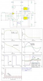
Here's the file for APEX HX-11 Class-H Amp.
Regards,
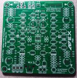
Why does this amp pcb have two different voltages.
@apexaudio
Are STD03P/N simulation models from the simulator you use coded or publicly available? I am looking for such to LTspice.
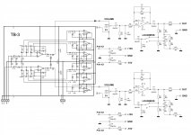
Hi, the simulation in TinaTI was done with macros for STD03N/P modeled by me then,
they work for me adequately and the macros adhere satisfactorily to DS parameters and curves,
so that Vbe_multi with built-in ThermalTrack diodes work as expected
and express the expected Vbe_multi voltage
I added a 10R R26 series resistor with a BIAS ADJ trimpot for OPS bias
on which we can check the bias current of ThermalTrack diodes,
around about 2-3mA,
so that we can correct the flow through R8-R12 (150R + 150R) and adjust their VAS bias current sharing
MJE340 / 350 can be exchanged for any other good VAS BJTs
let's say/or similar:
1381/3503 (2SA/2SC or KSA/KSC)
https://www.digikey.si/product-detail/en/on-semiconductor/KSA1381ESTU/KSA1381ESTU-ND/1050068
https://www.digikey.si/product-detail/en/on-semiconductor/KSC3503DSTU/KSC3503DSTUFS-ND/1049721
.SUBCKT STD03N 1 2 3 4
**************************************
* Model Generated by Dragan100 *
**************************************
* Model generated on May 23, 2015
* MODEL FORMAT: SPICE3
* Darlington macro model with Traking diods
* External node designations
* Node 1 -> Collector
* Node 2 -> Base
* Node 3 -> Emitter
* Node 4 -> Trak
Q1 1 2 5 qmodel
Q2 1 5 3 q1model area=15.45
D1 2 4 dmodel
R1 5 3 82
.MODEL dmodel d
+IS=4.352E-9 N=1.906 BV=110 IBV=0.0001
+RS=0.6458 CJO=7.048E-13 VJ=0.668
+M=0.03 FC=0.5 TT=3.48E-9 KF=0 AF=1
.MODEL qmodel npn
+IS=2.65841e-11 BF=137.033 NF=1.05607 VAF=30
+IKF=0.152356 ISE=2.80914e-13 NE=1.34324 BR=5.15385
+NR=1.5 VAR=14.2324 IKR=0.676264 ISC=2.80914e-13
+NC=1 RB=0.101363 IRB=0.212211 RBM=0.101363
+RE=0.267757 RC=1.33878 XTB=0 XTI=3.93844 EG=1.05
+CJE=1e-11 VJE=0.75 MJE=0.33 TF=1e-09
+XTF=1 VTF=10 ITF=0.01 CJC=1.01668e-09
+VJC=0.64861 MJC=0.23 XCJC=0.9 FC=0.5
+TR=1e-07 PTF=0 KF=0 AF=1
.MODEL q1model npn
+IS=2.56839e-13 BF=108.329 NF=0.983777 VAF=30
+IKF=0.181174 ISE=1e-16 NE=1.5137 BR=0.1
+NR=1.5 VAR=43.732 IKR=1e-05 ISC=1e-16
+NC=1 RB=4.93406 IRB=26.7409 RBM=4.93406
+RE=0.0001 RC=3.37191 XTB=0.705012 XTI=4 EG=1.206
+CJE=1e-11 VJE=0.75 MJE=0.33 TF=1e-09
+XTF=1 VTF=10 ITF=0.01 CJC=0
+VJC=0.635756 MJC=0.23 XCJC=0.9 FC=0.5
+TR=1e-07 PTF=0 KF=0 AF=1
.ENDS STD03N
.SUBCKT STD03P 1 2 3 4
**************************************
* Model Generated by Dragan100 *
**************************************
* Model generated on May 23, 2015
* MODEL FORMAT: SPICE3
* Darlington macro model with Traking diods
* External node designations
* Node 1 -> Collector
* Node 2 -> Base
* Node 3 -> Emitter
* Node 4 -> Trak
Q1 1 2 5 qmodel
Q2 1 5 3 q1model area=15.45
D1 4 9 dmodel
D2 9 8 dmodel
D3 8 7 dmodel
D4 7 6 dmodel
D5 6 2 dmodel
R1 5 3 82
.MODEL dmodel d
+IS=82.9n RS=2.02 BV=30.0 IBV=10.0u
+ CJO=12.802E-12 M=.47462 VJ=.6915 N=1.04
+TT=4.32p XTI=2 EG=0.69
.MODEL qmodel pnp
+IS=2.65841e-11 BF=137.033 NF=1.15607 VAF=30
+IKF=0.152356 ISE=2.80914e-13 NE=1.34324 BR=5.15385
+NR=1.5 VAR=14.2324 IKR=0.676264 ISC=2.80914e-13
+NC=1 RB=0.101363 IRB=0.212211 RBM=0.101363
+RE=0.267757 RC=1.33878 XTB=0 XTI=3.93844 EG=1.05
+CJE=1e-11 VJE=0.75 MJE=0.33 TF=1e-09
+XTF=1 VTF=10 ITF=0.01 CJC=1.01668e-09
+VJC=0.64861 MJC=0.23 XCJC=0.9 FC=0.5
+TR=1e-07 PTF=0 KF=0 AF=1
.MODEL q1model pnp
+IS=2.65841e-11 BF=137.033 NF=1.15607 VAF=30
+IKF=0.152356 ISE=2.80914e-13 NE=1.34324 BR=5.15385
+NR=1.5 VAR=14.2324 IKR=0.676264 ISC=2.80914e-13
+NC=1 RB=0.101363 IRB=0.212211 RBM=0.101363
+RE=0.267757 RC=1.33878 XTB=0 XTI=3.93844 EG=1.05
+CJE=1e-11 VJE=0.75 MJE=0.33 TF=1e-09
+XTF=1 VTF=10 ITF=0.01 CJC=0
+VJC=0.64861 MJC=0.23 XCJC=0.9 FC=0.5
+TR=1e-07 PTF=0 KF=0 AF=1
.ENDS STD03P
hi i haave made p30 alex mm pcb when i powered it two 22ohm resistors heated and smoked up. its fourth time i have made it every thing is ok. i have also rotted 2n5551. can any one help
hi i haave made p30 alex mm pcb when i powered it two 22ohm resistors heated and smoked up. its fourth time i have made it every thing is ok. i have also rotted 2n5551. can any one help
Have you checked the orientation of the 4148 diodes?
I'm assembling the ax11 layout, but I can't lower the bias that is at 330mv on resistor 0r22. I have already replaced the BC 139 and BC140 polarization transistors with MJE340 and MJE350, but it did not solve it. What can be done?

Last edited:
Have you checked the orientation of the 4148 diodes?
yes i have checked and also buffer circuit work good. i have attached the file.
Attachments
yes i have checked and also buffer circuit work good. i have attached the file.
any one who have made p30
I'm assembling the ax11 layout, but I can't lower the bias that is at 330mv on resistor 0r22. I have already replaced the BC 139 and BC140 polarization transistors with MJE340 and MJE350, but it did not solve it. What can be done?
View attachment 824542
Replace 4k7 with 3k3...
Have you checked the orientation of the 4148 diodes?
its now working the gain seems too high i have attached a apeaker to p30 to test.
the sound distorts at high volume. is it due to the speaker i have conected?
any one reply please
I don't understand. The P30 is a preamp. It's not meant to drive a speaker.its now working the gain seems too high i have attached a apeaker to p30 to test.
the sound distorts at high volume. is it due to the speaker i have conected?
any one reply please
I don't understand. The P30 is a preamp. It's not meant to drive a speaker.
Jupp, 🙂
with an expected max 50mApeak of output current,
he can even expect a few tens of mW on 8R0 output load of the P30 preamp.
Most likely, the output will go in current clipping as early as with 0.5Vpeak
output voltage amplitude with such a low output load!
- Home
- Amplifiers
- Solid State
- 100W Ultimate Fidelity Amplifier