Hello,
I am reading from different sources that having higher voltages than what is mentioned in the service manuals is kind of a common thing nowadays as the wall outlet voltage has slightly increased and some even say that having slightly higher voltages is normal with the Fisher gear. However my situation is slightly different.
As for starters, I do not have the right service manual. This manual I have attached belongs to the earlier set of serial numbers. So, I am not 100% sure if these voltages are correct for this X-202-C. However, for 7591 the B+ is around 440V which is as mentioned in the service manual. What I am measuring at the tube pins is 490V. This is of course by controlling the line voltage with a variac set to deliver 120V at the amplifier input. As this is the voltage right after the Fishers’ infamous voltage doubler and the diodes check out ok, I have experimented with inserting a 22ohm 25W resistor between the capacitor and the diode. By this way I am able to bring down the 490V to 440V. And I am not stopping there, I am also increasing the next resistor in line from 1.5kohm (Which measured within tolerance) to 2.7kohm and having the 390V right. After that point all, the voltages fall into their places.
My question is, am I doing something that may cause other issues, or can this amplifier live to see another day with these modifications? I am worried because with these high voltages, I see slight red glow on the sides of the 7591 tubes, and I am worried it may shorten the tube life.
Thanks,
Dirk
Attachments
Dirk,
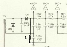
The dropping resistor idea is reasonable, but you have the 22 Ω part in the wrong place. Fisher employed a "full wave" voltage doubler, which (in fact) is a pair of 1/2 wave rectifiers wired back to back. As shown, you are dropping the O/P of only 1 of the 1/2 wave blocks. You need to move that main dropping resistor into the line between the power transformer and the junction of C26 and C27A. Placed there, the part impacts on both 1/2 wave rectifier blocks. You may have to adjust your dropping parts' values, after relocating the main dropping resistor, in order to obtain the desired results.
Another place to check for over voltage is in the heater supplies. You want 6.3 VAC +5%/-10%. The same %s apply to 25 VDC. Additional dropping parts may be needed. Keep the need to maintain existing symmetries in mind.
Consider replacing R75 with a 5Kohm linear taper potentiometer. You gain control over the O/P tube bias voltage. You will still need well matched quartets of 7591s, but slight "red plating" can be curbed, particularly as the tubes age.
As current production 7591s are intolerant of the liberties Fisher frequently took with the 7591's grid to ground resistance limit, I direct your attention here.
The added dropping resistors will "manufacture" heat. Employ a low noise fan to keep the air associated with the unit moving. Unwanted heat build up is a mortal enemy of all things electronic.
Attachments
At what voltage on the variac are the voltages in the amp OK? Isn't this a perfect case for a bucking transformer? My view is moving away from the original design for a classic amplifier is not really an ideal solution.
The odds are very long that Fisher's original design took liberties with the 7591 grid to ground resistance limit. As current production 7591s are prone to runaway, when those liberties are present, changes that ensure reliable operation must be made.
Hens' teeth are easier to source than OS 7591s.
Hens' teeth are easier to source than OS 7591s.
Sure, with a line voltage to high not only the HT is involved but also the heater voltage.At what voltage on the variac are the voltages in the amp OK? Isn't this a perfect case for a bucking transformer?
Mona
At what voltage on the variac are the voltages in the amp OK? Isn't this a perfect case for a bucking transformer? My view is moving away from the original design for a classic amplifier is not really an ideal solution.
I see your point. I have observed that when I hit 110V at the variac, all the voltages are within 2-5% of what they should be. The transformers for stepping down US mains to Japanese mains is something I am considering. But, it is just an external component and 2 resistors are much more compact and cheap.
/Dirk
I’ve seen examples where the bucking transformer is added before the primary. It is just to have two 115v primary windings and a secondary winding equivalent to the required voltage drop.Sure, with a line voltage to high not only the HT is involved but also the heater voltage.
Mona
Dirk,
The dropping resistor idea is reasonable, but you have the 22 Ω part in the wrong place. Fisher employed a "full wave" voltage doubler, which (in fact) is a pair of 1/2 wave rectifiers wired back to back. As shown, you are dropping the O/P of only 1 of the 1/2 wave blocks. You need to move that main dropping resistor into the line between the power transformer and the junction of C26 and C27A. Placed there, the part impacts on both 1/2 wave rectifier blocks. You may have to adjust your dropping parts' values, after relocating the main dropping resistor, in order to obtain the desired results.
Another place to check for over voltage is in the heater supplies. You want 6.3 VAC +5%/-10%. The same %s apply to 25 VDC. Additional dropping parts may be needed. Keep the need to maintain existing symmetries in mind.
Consider replacing R75 with a 5Kohm linear taper potentiometer. You gain control over the O/P tube bias voltage. You will still need well matched quartets of 7591s, but slight "red plating" can be curbed, particularly as the tubes age.
Hello Eli,
Thank you for the elaborate response.
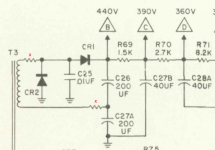
If I understand you correctly, you are correcting my resistor location to the one which is across the two capacitors, like I shared below. I believe this arrangement will require a different resistor value. I will experiment with it.
As for the bias, with the high voltages it is at -19V when I drop them it settles at -17V. And interestingly the heater voltages are correct.
/Dirk
Attachments
I wouldnt do what you're doing - now the piece isnt in original condition, which drops its value. Also when you start mucking with the dropping resistors in the power supply, you're changing the dynamic character of that part - who knows what that does to how it sounds?
Much easier work-wise is to arrange a 6.3V or 12.6V transformer to "Buck" the AC line voltage down those few volts, to match what the X-202 wants to see AC line wise. (The current capacity of the buck transformer needs to be capable of handing the steady state AC current of the X-202)
This way, you can run and use it as if you had the variac connected all the time, dialed in to a better AC line voltage for it. Such an arrangement could be a box in the AC cord of the X-202 -
I wouldnt do what you're doing - now the piece isnt in original condition, which drops its value.
Is the value in making music or gathering dust on a shelf? Reliable operation with current production 7591s is not possible, unless some sort of modification is made. OS 7591s are made from "unobtainium".
While you are at it, never replace overage OEM electrolytic capacitors that have dried out and will destroy the unit, if it is turned on.
To drop some voltage your resistor (22Ω ?) should be in one of these places.If I understand you correctly, you are correcting my resistor location to the one which is across the two capacitors, like I shared below. I believe this arrangement will require a different resistor value. I will experiment with it.
Mona
Attachments
Hello Eli,
Thank you for the elaborate response.
If I understand you correctly, you are correcting my resistor location to the one which is across the two capacitors, like I shared below. I believe this arrangement will require a different resistor value. I will experiment with it.
As for the bias, with the high voltages it is at -19V when I drop them it settles at -17V. And interestingly the heater voltages are correct.
/Dirk
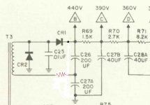
Negative! What you show can cause damage. You maintain symmetry between the 2 1/2 wave blocks by placing the main dropping resistor as shown in my upload.
Clearly, the entire negative supply needs tending to. If the bias voltage applied to the O/P tubes' control grids is low, the cathode current is too high and red plates result. If anything, the bias voltage should be higher than the OEM value. Better to loose some power O/P than have a failing tube destroy the associated O/P transformer.
Methinks every last electrolytic capacitor in the unit should be replaced. Remember, 'lytics literally dry out over time.
If you can tolerate the notion of small parcels being shipped from the U.S. to Belgium, contact Jim McShane. Jim is a valuable resource, when somebody is engaged in this sort of project.
Attachments
Hello Ketje and Eli,
Thank you for warning me before making a mistake. I can follow the thinking behind this voltage doubler better now. I will take your advice and try to see what I can do about the 440V first.
Also, I didn’t want to start the Holly war between the purist and the functionalists. I know the value of staying loyal to the original design as that is what I am after. After all, I am restoring this TOTL Fisher amplifier to get a taste of how the equipment was voiced back in the day. I am using period correct solder material and ordered my replacement caps from Hayseed Hamfest. They are all in now and I am even paying attention to the direction of the capacitors while replacing them.
The voltages made me nervous because if they are outside the limits of the service manual mentioned values due to the increase in the line voltage, it occurred to me as a better idea to tackle them in the chassis.
Best,
/Dirk
Attachments
Stay loyal to the spirit of Fisher's design, but end up with a reliable, functional, piece of equipment. Stone cold original can't be functional in today's environment.
Somebody in the EU using 60/40 Sn/Pb solder. Oh the horror! 😀 Take care, lest the "Secret Police" beat your door down.
Somebody in the EU using 60/40 Sn/Pb solder. Oh the horror! 😀 Take care, lest the "Secret Police" beat your door down.
I wouldnt do what you're doing - now the piece isnt in original condition, which drops its value. Also when you start mucking with the dropping resistors in the power supply, you're changing the dynamic character of that part - who knows what that does to how it sounds?
Much easier work-wise is to arrange a 6.3V or 12.6V transformer to "Buck" the AC line voltage down those few volts, to match what the X-202 wants to see AC line wise. (The current capacity of the buck transformer needs to be capable of handing the steady state AC current of the X-202)
This way, you can run and use it as if you had the variac connected all the time, dialed in to a better AC line voltage for it. Such an arrangement could be a box in the AC cord of the X-202 -
How about placing a huge chunk of an inductor on the line path of this amplifier? That would change the behavior of the amplifier too.
Anyway, I have done some experimenting with the resistors at the spots which were suggested by Ketje and Eli. What I am observing is, even the 50W resistors are getting to hot to touch. They are about 45-55dgC and it is not really easy to find a nice spot for them under the chassis. Although I have the wooden case to conceal them, I don’t want to run cables to the transformer side and place them on the top of the chassis, which will look like an amateur job.
With more unknowns that will arise from the inductive component in line with the amplifier, I think I will lean towards a step down transformer (120V to 100V) to keep the voltages under control and leave everything as original inside.
Best,
Dirk
 Thread reopened by member request.
Hello DirkSpec. i am having the same issue on my x-202-c rebuild project. Mine too is a later serial number than the schematic readily available on the internet for the lower serials. I am curious how you finally resolved the higher voltages? Also, does anyone know the consequences of running the unit at the higher voltages as I suspect they were at these higher values even before I started the rebuild. Thanks
Documenting here for posterity. As mentioned further up in the thread I think my issue is incoming line voltage being quite a bit higher than in 1965. After experimenting with different bulb wattages in my dim bulb tester and comparing line voltages to various power supply voltages, I got confident enough to reinstall my 7591 output tubes and take some more readings. I was surprised how much putting in the tubes changed the voltages in the unit. I’m now about 10% over the schematic voltages with the 7591s in place and with line voltage at 123 vac. Based on experiments it looks like I should be able to get to the schematic voltages at 117 vac line voltage which is what I understand the schematic voltages are based on, so I’m thinking the restoration work is good. question remaining is what is the risk of running the unit on existing 123 vac line voltage vs buying a variac and turning it down to 117? Any advice greatly appreciated!
If you use the amp a lot, it maybe worthwhile to use a Variac.
But if there is only occasional use, probably that is not necessary.
But if there is only occasional use, probably that is not necessary.
- Home
- Amplifiers
- Tubes / Valves
- Fisher X-202-C Restoration: Power Supply Voltages too High