Dear builders,
I have been playing with the idea of building a tube amplifier on a vertical plan. PT and OPT's can be bought cheaper, without covers (they sit on the lower floor, inside the case), tubes on top, the foot-print would be smaller. Would be valid for a pair of monoblocks or a stereo amp. An integrated amp would maybe have the input module and tubes at the back, the power tubes at the front (or the other way but then input cables are longer from back-sockets).
I have seen a few examples online :
- The 6EM7 Vertical Amp | Cascade Tubes (Matt's nice woodworking)
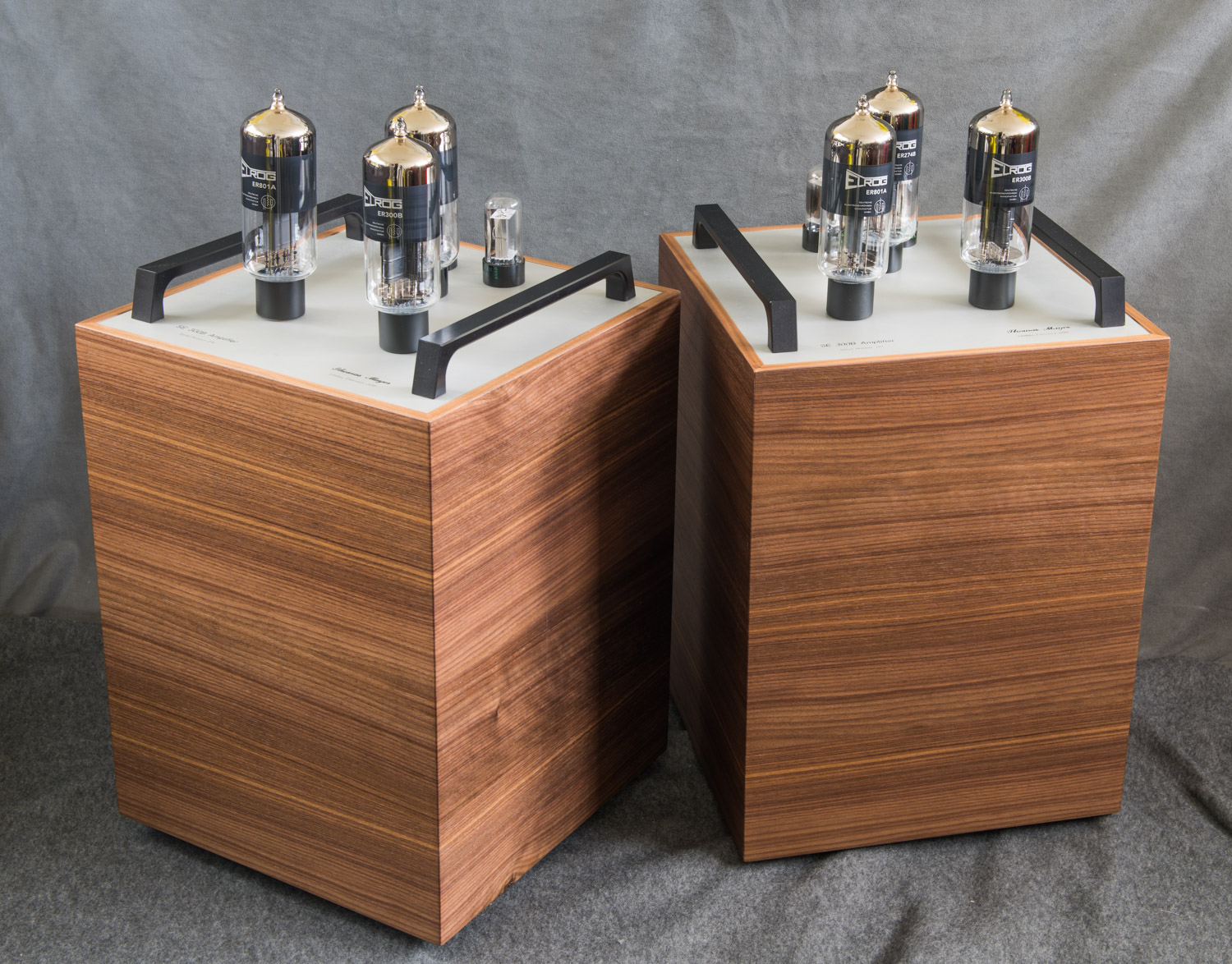
- 300B Amplifiers by Thomas Mayer - VinylSavor - Thomas Mayer (Thomas Mayer of Elrog fame)
- Reference 750 SEL Mono Amplifier from Audio Research (look for the pic of the opened sides)
Always nice to see more DIYers in Switzerland!
Besides "heat management" I do not see any problem with a vertically mounted amplifier.
With heat management I mean that the lower deck would contain the cold components (OPT is an example) or components that like it cold (power supply capacitors). The nicely looking and hot tubes go on top, their heat never reaching the lower deck (an advantage of vertical mounting). The power supply transformer can become quite warm, but probably still ok to put on the lower deck, far from the PS capacitors.
A possible problem of vertical mounting is reaching the components for mounting and soldering. Some construction with hinges may help! Or, do as the 6EM7 example, which is basically a traditional "horizontal amp" standing.
good luck,
Erik
Many high power valves have limitations on mounting orientation given in the datasheet - be sure to check this (sagging of hot filaments/parts being the issue I believe). Don't mount mount tubes in a vertical stack, the top ones will cook in the hot-air plume of the lower ones.
In the tube TV era, thousands of them used vertical chassis, parallel to the front of the CRT. So the idea is old and may perform very well.
My next amplifier needs to be movable so I am planning to use one of these with the trays installed upside down. Power supply on the bottom shelf, output transformers on the middle shelf and tubes at the top.
RASKOG Trolley - white - IKEA
My wife says that these Raskog trolleys are very popular with her craft friends and are very sturdy.
As you get older, you have to think more about the weight of your amplifiers.
ray
RASKOG Trolley - white - IKEA
My wife says that these Raskog trolleys are very popular with her craft friends and are very sturdy.
As you get older, you have to think more about the weight of your amplifiers.
ray
I have made a few non traditional amps. Most were done in attempt to reduce the footprint on my very limited horizontal bench / shelf space.
I built one I called the Double Decker. It made about 100 WPC and used several small power transformers to get the required voltages. All of them and the solid state power supply were directly mounted to the floor of a 5 sided wood box. The ugly looking power supply was made on perf board, but it and the collection of EI and toroidal transformers, including the open frame OPT's were hidden inside the box.
The top plate was aluminum with 12 tubes sticking out of the top, much like a conventional amp. It existed for a year or two before I decided to rip it up for its parts.....it just looked funny, like a conventional amp with no transformers and a tall base. The proportions were all wrong and it didn't save much space.
I was digging through the warehouse one day when I found my long forgotten solid state stereo system from the 1980's. There was a Technics Tuner, a Phase Linear 4000 Autocorrelating Preamplifier, and a Carver M-400 "Magnetic Field Amp." AKA, the Carver Cube. I would wind up giving all of it to a friend, except the tuner which I still have, but...…
Why couldn't I make Tubelab Cube. I had already figured out how to wire both channels of a Tubelab SPP in parallel, run them from a fat Antek toroid on about 430 volts (way over spec for an EL84) and get about 60 clean watts of glorious mono power. Continuous abuse with a guitar preamp didn't blow it up, so I built two boards, ran them from a bigger Antek toroid for a stereo 120 watt amp. I never believed that it would live long, so I made a rather crude, but unique cube shaped box for it all in wood shop class one night, then cut up all the metal the following week.
This thing lived on for 4 or 5 years with no issues, despite being used for a guitar amp a lot. But like many of my projects something newer and shinier comes along and kicks it out of the system. In this case it was several versions of Pete's Big Red Board. The cube wound up in the closet, lonely and ignored, and eventually robbed for its parts. One of the SPP boards became a smaller guitar amp, the OPT's went in a Pete amp, then got stolen again and now reside in a test amp that I made.
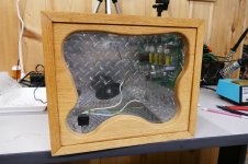
The Cube still sits on a shelf, lonely and ignored. I got it down, dusted it off, and took these pictures. Reflections from the bench lights kinda make it look dirtier than it really is. I kept this box for it's uniqueness. I will put something cool inside someday, maybe a guitar amp.
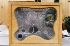
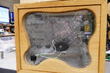
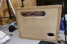
The wood is all Oak. Unlike Carver's Cube, this amp DOES put out some heat, so the top and bottom are routed out and covered with a metal grille. There were rubber feet on the bottom allowing for air to enter, and exit from the top. The front is .062 Lexan so that everything inside is visible. The back, and both sides are lined with aluminum Diamond Plate. The entire metal chassis assembly slides out from the rear just by yanking on the speaker terminals. One SPP board still lives inside the box, but everything else is gone. The black disk in the back is the mount for the Antek toroid. The shiny black OPT's lived in the lower rear corners.
There was a RGB LED strip mounted to the rear of the front panel facing rearward to light up the insides, and some Electro Luminescent wire inside the milky white tubing that carried all the internal wiring. I liked the blinkin light effects for guitar, but they were too distracting for HiFi.
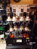
Most directly heated tubes have restrictions on how they can be mounted horizontally. Cheap 300B's don't like it at all, the filament sags when hot and can touch the grid. As you see here, mount the hottest tubes above the driver tubes. These boards did not use a rectifier tube. True 5AR4's with a cylindrical cathode sleeve can be used horizontally. 5U4's and 5Y3's risk a filament to plate short when the filament goes open, which will scatter your filter cap all over the amp.
Some of the typical indirectly heated tubes can eventually warp the cathode over many heating - cooling cycles, and should be mounted such that their grid wires run vertically to minimize this. The problem comes when two different brands of tubes have their guts mounted differently. This amp ran 8 X Baldwin branded Sylvania 6BQ5's which were removed from a dead church organ. The were mounted as shown, and are all still alive today.
I also mounted several amps inside 2 RU chassis, and 3 RU rack mount computer chassis. This makes for more efficient space utilization. I did this with an SSE board by mounting the output tubes horizontally on a piece of aluminum angle. It works, but a class A SE amp puts out a LOT of heat. It is not wise to put your hand on the top surface of that amp after it's been on all day.
I built one I called the Double Decker. It made about 100 WPC and used several small power transformers to get the required voltages. All of them and the solid state power supply were directly mounted to the floor of a 5 sided wood box. The ugly looking power supply was made on perf board, but it and the collection of EI and toroidal transformers, including the open frame OPT's were hidden inside the box.
The top plate was aluminum with 12 tubes sticking out of the top, much like a conventional amp. It existed for a year or two before I decided to rip it up for its parts.....it just looked funny, like a conventional amp with no transformers and a tall base. The proportions were all wrong and it didn't save much space.
I was digging through the warehouse one day when I found my long forgotten solid state stereo system from the 1980's. There was a Technics Tuner, a Phase Linear 4000 Autocorrelating Preamplifier, and a Carver M-400 "Magnetic Field Amp." AKA, the Carver Cube. I would wind up giving all of it to a friend, except the tuner which I still have, but...…
Why couldn't I make Tubelab Cube. I had already figured out how to wire both channels of a Tubelab SPP in parallel, run them from a fat Antek toroid on about 430 volts (way over spec for an EL84) and get about 60 clean watts of glorious mono power. Continuous abuse with a guitar preamp didn't blow it up, so I built two boards, ran them from a bigger Antek toroid for a stereo 120 watt amp. I never believed that it would live long, so I made a rather crude, but unique cube shaped box for it all in wood shop class one night, then cut up all the metal the following week.
This thing lived on for 4 or 5 years with no issues, despite being used for a guitar amp a lot. But like many of my projects something newer and shinier comes along and kicks it out of the system. In this case it was several versions of Pete's Big Red Board. The cube wound up in the closet, lonely and ignored, and eventually robbed for its parts. One of the SPP boards became a smaller guitar amp, the OPT's went in a Pete amp, then got stolen again and now reside in a test amp that I made.
The Cube still sits on a shelf, lonely and ignored. I got it down, dusted it off, and took these pictures. Reflections from the bench lights kinda make it look dirtier than it really is. I kept this box for it's uniqueness. I will put something cool inside someday, maybe a guitar amp.
The wood is all Oak. Unlike Carver's Cube, this amp DOES put out some heat, so the top and bottom are routed out and covered with a metal grille. There were rubber feet on the bottom allowing for air to enter, and exit from the top. The front is .062 Lexan so that everything inside is visible. The back, and both sides are lined with aluminum Diamond Plate. The entire metal chassis assembly slides out from the rear just by yanking on the speaker terminals. One SPP board still lives inside the box, but everything else is gone. The black disk in the back is the mount for the Antek toroid. The shiny black OPT's lived in the lower rear corners.
There was a RGB LED strip mounted to the rear of the front panel facing rearward to light up the insides, and some Electro Luminescent wire inside the milky white tubing that carried all the internal wiring. I liked the blinkin light effects for guitar, but they were too distracting for HiFi.
high power valves have limitations on mounting orientation given in the datasheet
Most directly heated tubes have restrictions on how they can be mounted horizontally. Cheap 300B's don't like it at all, the filament sags when hot and can touch the grid. As you see here, mount the hottest tubes above the driver tubes. These boards did not use a rectifier tube. True 5AR4's with a cylindrical cathode sleeve can be used horizontally. 5U4's and 5Y3's risk a filament to plate short when the filament goes open, which will scatter your filter cap all over the amp.
Some of the typical indirectly heated tubes can eventually warp the cathode over many heating - cooling cycles, and should be mounted such that their grid wires run vertically to minimize this. The problem comes when two different brands of tubes have their guts mounted differently. This amp ran 8 X Baldwin branded Sylvania 6BQ5's which were removed from a dead church organ. The were mounted as shown, and are all still alive today.
I also mounted several amps inside 2 RU chassis, and 3 RU rack mount computer chassis. This makes for more efficient space utilization. I did this with an SSE board by mounting the output tubes horizontally on a piece of aluminum angle. It works, but a class A SE amp puts out a LOT of heat. It is not wise to put your hand on the top surface of that amp after it's been on all day.
Attachments

Last edited:
I have also been exploring ways to keep the footprint down.
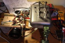
The only approach I have tried so far is to create a box 24cm * 20cm * 20cm that contains all the transformers. The OPT's are on their sides on each side and the centre space contains the power trasformer, which is horizontal and the choke above that, with space for a motor run capacitor and some power supply components.
The amp is a point-to-point version of an SPP using 15v output tubes (PL84), built in a fancy baking tray I found in recycling.
I have had problems with the screen voltages. That led to exploring regulator circuits (I ended up using the schema from the Red Light District amplifier), but then it is not much point using my fancy ultralinear toroids in that amp, so then I decided I will re-implement it with cheaper power toroids for OPTs, running the tubes in pentode mode.
Even combining so much in the base, it was still quite large.
My next plan is to take the Dissident audio ECL86 amp, and use PCL86 and create two compact amplifiers, each with an integral toroid, that can be mounted on its side in a box (i.e. have the tubes mounted side ways). I have been looking at some old reel-to-reel tape recorders, getting some inspiration for how they pack the different stages around the motor.
Another option I have considered is to get potted toroids, and to use them as the feet of an amplifier. It will be a bit like a fancy turntable, with 3 large feet (OPTs at the front, power trasformer at the back. Then ifthey can be buried into a wood block, the electronics can be built on top of that.
Yet another option is to build inside an old radio cabinet, but if you are like me you will struggle to bring yourself to canibalise something like that.
As you can probably guess, too many ideas, too little time ;-(
Attachments
Last edited:
.I have had problems with the screen voltages
The previously mentioned SPP ran the plate supply voltage to the EL84 / 6BQ5's at 430 volts. The screen voltage when doing that needs to be around 200 to 250 volts (don't remember the exact number since I built it many years ago). I used a simple mosfet follower fed by a Zener string and a pot. Set the pot for the best compromise between dissipation, power output, and distortion.
I do the same thing on my TV sweep tube amps.
In the tube TV era, thousands of them used vertical chassis, parallel to the front of the CRT. So the idea is old and may perform very well.
The Fin de siècle of vacuum valves' innovation was the climactic Compactron era, after the Dinosaurs but before the Internet. Maybe goofy, but we can't do it today - or go to the moon. I-phones aren't actually technology.
All good fortune,
Chris
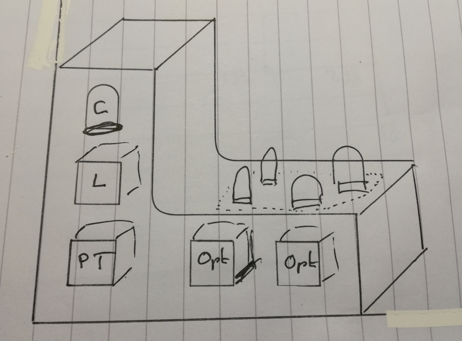
Thanks all for your ideas, build pics and hints. See as well the "Manley Absolute Headphone Amp" which has an interesting "L" layout. I could imagine something like that one, with the back/vertical space being used for PT, choke and capacitor can, while the tubes sits on top of the OPTs.
Quick sketch... no I'm not a designer 🙂
oohh, and I didn't make me clear, the tubes would always be on top, and sit vertically.
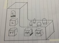
Quick sketch... no I'm not a designer 🙂
oohh, and I didn't make me clear, the tubes would always be on top, and sit vertically.
Attachments

Vertical chassis didn't work too well with the RCA CTC5 series early color TV sets...the two 5U4 rectifiers dumped off a lot of heat for starters...wax melting off some of the capacitors...the heat in the HV cage didn't help the flyback transformer any...
nice, heavy, solid welding job! Actually I can do stick welding but I doubt I would find the crane to move this around 🙂
... I doubt I would find the crane to move this around 🙂
you are right, that's why it has wheels🙂

Photo by Holger Barske
ff2010/hb/DSC_0179
Last edited:
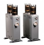
Your "neighbor" Nagra-Kowalsky maked beautiful vertical layout power amplifiers with different output tubes.
As is well known, Nagra is a world miracle of electromechanics.
I wasn't aware Nagra did amps as well, they were known for the tape recording devices when I was a young engineer. Interesting design... look the inside from their web, toroids PT and OPT it seems, and all tubes are vertical.
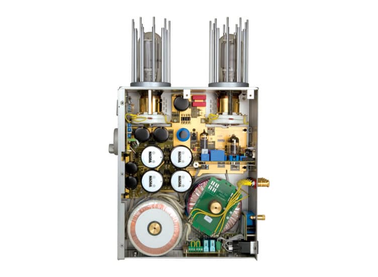
Edit : multiple pics on Nagra VPA 845 - Le forum Audiovintage
Last edited:
Yes. I watched their amplifier with 300B tubes.
I "resent" for Nagra that they were picking up a huge amount of Russian 6H30 tubes in Russia, (which Nagra uses for input/driver tubes, mostly). So they raised the price of 6H30 very much on the market 🙂
Best DIYing
I "resent" for Nagra that they were picking up a huge amount of Russian 6H30 tubes in Russia, (which Nagra uses for input/driver tubes, mostly). So they raised the price of 6H30 very much on the market 🙂
Best DIYing
- Home
- Amplifiers
- Tubes / Valves
- vertical layout for a tube amp