That was my first thought, that got replaced with a sealed 5k bournes multiturn, it got recapped whilst the board was out as well.
Compare the voltages between channels, it might be revealing as to the source of the issue. I have seen that poor connections (oxidized contacts) can cause these bias issues. I see you have a connector to the output stage (OPS) and you probably have TO-3 sockets for the OPS devices as well, so clean them up and see where that gets you.
Are you sure that the amp isn't oscillating? Are all the various electrolytic bypass caps towards the frontend in good shape? This can be a weak spot on some of these old Kenwoods.
Apart from that, these units seem to be plagued by lots of bad joints in the first series (S/N 1xxxx), as well as those crappy black ceramic caps that have a tendency towards literally falling apart if memory serves (the same ones that plague the Sansui AU-X1, I guess - or was it the tuner TU-X1?).
Apart from that, these units seem to be plagued by lots of bad joints in the first series (S/N 1xxxx), as well as those crappy black ceramic caps that have a tendency towards literally falling apart if memory serves (the same ones that plague the Sansui AU-X1, I guess - or was it the tuner TU-X1?).
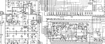
Update on this, as mentioned these are plagued by bad joints on the x07-1770 board, this board is a two-layer board made by Elna and is of very poor quality the solder joints lift completely off the pad which is what caused the bias to be high not to adjust properly. I ended up scraping the oxidation off the solder pads to get a good joint as my cleaning materials and fibreglass brush would not touch it.
It also did have those black ceramic caps on the same board, commonly known as black flag caps, these got replaced with silver mica caps.
It also did have those black ceramic caps on the same board, commonly known as black flag caps, these got replaced with silver mica caps.
Well..... Problems with the Bias again, it will not adjust it just seems to be stuck at 3.2mv. Also, the speaker protect relay will not engage, this is controlled by a Hitachi Ha12002.
All power supply voltages check out ok and all transistors within the power amp check out ok.
Anywhere else I should be looking?
All power supply voltages check out ok and all transistors within the power amp check out ok.
Anywhere else I should be looking?
Look at the data sheet for the ha12002, pin1 goes low under normal operation. Under a fault the pin floats as it is a open collector pin. Check the input pins, if they are diven, above the threshold voltage, it is a fault condition, need to be determined the cause.
Doesn't look like it. It just seems to disconnect the global feedback.Will this protection circuit limit the bias if its in protection?
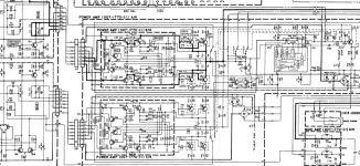
I'd say make sure that the protection has no reason for activating. By the looks of it it merely goes on output DC offset for both channels and AC presence (rectified voltage at D15), so make sure those are OK.
Check the Zobel networks (R53 - C5 and R54 - C6, 10R / 3W and 39n respectively).
Given the history I wouldn't be surprised to see another bad connection.
Should protection engage without any good reason, usually it's just a random bad component in there. Could mean more via fun.
OK, voltage on pins of HA12002, any seem out of the ordinary for anyone?
Pin 1 - 39.55v
Pin 2 - 0.328mv
Pin 3 - 776.4mv
Pin 4 - 0.780mv
Pin 5 - 2.66v
Pin 6 - 84.42mv
Pin 7 - 6.95v
Pin 8 - 30.85mv
Pin 1 - 39.55v
Pin 2 - 0.328mv
Pin 3 - 776.4mv
Pin 4 - 0.780mv
Pin 5 - 2.66v
Pin 6 - 84.42mv
Pin 7 - 6.95v
Pin 8 - 30.85mv
Did you do as I suggested, download/read/understand the datasheet?
This part accepts -ve voltages, do not use "-" as your delimiter, use something like ":"
Pin 5 - 2.66v is confusing, is it,
Pin 5 : +2.66v or -2.66V?
There is to be a -ve supply half wave rectifier for pin 5, for use as your AC presence detection, look at the test circuit and the electrical voltages in the table above it. -10V max, threshold is -1.8,-1.2,0 VDC
Voltages from the service manual and my amplifier (Kenwood KA-80)... i had a broken HA12002 too. The voltage on pin 1 looks fishy ... check the transistor that drives it as well.
Pin 1 = 0V
Pin 2 = 0V
Pin 3 = 0V
Pin 4 = 0V
Pin 5 = -4V7
Pin 6 = 0V
Pin 7 = +7V2
Pin 8 = +5V6
Pin 1 = 0V
Pin 2 = 0V
Pin 3 = 0V
Pin 4 = 0V
Pin 5 = -4V7
Pin 6 = 0V
Pin 7 = +7V2
Pin 8 = +5V6
pin 1 is an open collector, Q16 in the datasheet, it is showing an open, or no drive, thus pin 1, is pulled up to the supply V, or close to it.
Did you do as I suggested, download/read/understand the datasheet?
This part accepts -ve voltages, do not use "-" as your delimiter, use something like ":"
Pin 5 - 2.66v is confusing, is it,
Pin 5 : +2.66v or -2.66V?
There is to be a -ve supply half wave rectifier for pin 5, for use as your AC presence detection, look at the test circuit and the electrical voltages in the table above it. -10V max, threshold is -1.8,-1.2,0 VDC
Better this way,
Pin 1 39.55v +
Pin 2 0.328mv +
Pin 3 776.4mv +
Pin 4 0.780mv -
Pin 5 2.66v -
Pin 6 84.42mv +
Pin 7 6.95v +
Pin 8 30.85mv +
I've measured the voltage on R55/56 going to the bases of Q15/16 R55 measures 30v either side, R56 measures 30v on the D14 side and 0.625 on the base of Q16 side. Does this mean that the transistor is turned on and the fault is likely in that channel of the amp?
Leaky bias diodes were a problem with this unit.
Short out diode string to check.
Jam
Do you mean D2 or D4? Short out to check meaning just connect anode to cathode and seeing if the voltages on that power amp card normalize?
Last edited by a moderator:
Okay so I downloaded the service manual so I have something to refer too.
I am not sure what bias diodes he is referring too, I have never worked on this unit.
Your voltages readings for HA12002 (IC1) do not look totally out of wack.
What are your DC offset V for each channel? you can measure at R57,58 which connect to the o/p's.
You can do a quick test, put a temp short across R61, to ensure that the DC offset input to IC1-4 is 0VDC.
I am leaning towards you have a defective HA12002 (IC1). Cheap enough, could remove the device, put in a SIP socket get ready to try out another one, have a cheap spare if it is not the reason why.
Okay, problem one solved, Q2 on the right power amp board was faulty, a quick scavenge of my used tranny box welded the correct part and presto relay now firing and signal now passing through to speaker terminals.
Now onto problem two, the low Bias, now as it's affecting both channels I'm thinking power supply or ground? Anyone point me in the general direction of where to start?
Now onto problem two, the low Bias, now as it's affecting both channels I'm thinking power supply or ground? Anyone point me in the general direction of where to start?
- Home
- Amplifiers
- Solid State
- Kenwood L-01A Bias