Greetings from a new member.
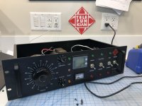
I have posted a video on YouTube describing the design and building of an Electronic Circuit Breaker (including schematic, PCB, BOM and Gerber files available) integrated with a Variac and Isolation Transformer in one 3 unit rack mount case. This equipment setup would be quite useful to anyone building, repairing or testing audio gear, especially tube circuits.
The electronic circuit breaker is based entirely on the Glasslinger circuit. It features an adjustable current limit (200mA to ~7 amps) and adjustable sensitivity (2 (~32msec) , 4, 16 or 32 cycles above the current limit) and is much faster than a fuse or mechanical circuit breaker. It uses a LM311 comparitor and a CD4040 binary counter to trigger a MOSFET that activates a cutoff relay.
This is my first YouTube video, feedback welcome! I hope you enjoy it.
Video Link:
YouTube
Attachments
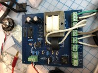
Glasslinger Electronic Circuit Breaker
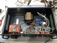
Yes of course, good point! There is an actual fuse in the chassis, at the back, which is the first thing the power sees prior to the power switch. I have a GFCI on my bench as well and then about 10 feet away from that is a mechanical circuit breaker. We are only dealing with about 120v here in North America, but you can never be too safe, especially when fixing tube amps and the like that often have 500v or more B+.
Do you back up the cb function with an actual fuse or cb?
Yes of course, good point! There is an actual fuse in the chassis, at the back, which is the first thing the power sees prior to the power switch. I have a GFCI on my bench as well and then about 10 feet away from that is a mechanical circuit breaker. We are only dealing with about 120v here in North America, but you can never be too safe, especially when fixing tube amps and the like that often have 500v or more B+.
I'd be concerned about using a polarised tantalum to effectively RC filter the AC output voltage of the secondary winding of the CT.
Also, note that testing was done with a resistive load, whereas you may be powering equipment with a rectified secondary that is input-capacitor filtered, and hence the mains AC current can have a very peaky waveform, which could mean tripping occurs at a much lower mains rms current level as the detection circuit is peak detect.
You may also want to confirm operation is as expected with a load with high in-rush current, such that the 311 doesn't get damaged from an input signal exceeding the power supply rails, and that the trip doesn't reset itself from the positive input exceeding common-mode level.
120V mains is just as unsafe as 240V mains.
I'd be concerned about using a polarised tantalum to effectively RC filter the AC output voltage of the secondary winding of the CT.
Also, note that testing was done with a resistive load, whereas you may be powering equipment with a rectified secondary that is input-capacitor filtered, and hence the mains AC current can have a very peaky waveform, which could mean tripping occurs at a much lower mains rms current level as the detection circuit is peak detect.
Yup, yup yup. Very strange way to "process" the output of an AC current transformer. One could add an active rectifier with switchable peak detection. Another option is to buy a surplus Hall based AC current transformer off eBay with the required specs. Unfortunately these options complicate the circuit for the small times the circuit will not "trip". A backup quick blow fuse is a necessity.
... concerned about using a polarised tantalum to effectively RC filter the AC output voltage of the secondary winding of the CT.
...
You may also want to confirm operation is as expected with a load with high in-rush current, such that the 311 doesn't get damaged from an input signal exceeding the power supply rails, and that the trip doesn't reset itself from the positive input exceeding common-mode level.
120V mains is just as unsafe as 240V mains.
trobbins... Thanks for your feedback. I'm not sure that I understand what you mean by your concerns related to the 'effective' filtration of the RC load? Do you mean in situations like you have described with a high in rush current as a result of capacitive loads on power transformers, or more generally? Can you elaborate? (thanks in advance) With high in rush current I might expect tripping, when set on the more sensitive settings. @ 32 cycles, ~500ms, I would expect the system to 'duck' the inrush current, as would a mechanical circuit breaker or a fuse. If what you are suggesting is a failure mode where the inrush blows the 311 so it fails to trigger, that could be a possibility, and I will see if I can rig up a test for that. The circuit I have used is certainly not perfect. Xraytonyb has a set of videos where he discusses, and addresses some of the issues associated with this, the Glasslinger circuit, which generated a lot of feedback on his channel showing that there are many approaches to this problem. I liked this circuit in part due to the simplicity, and the fact that Glasslinger has used it for so long in a relevant context helped put me at ease. Included among his uses, the repair of transformer powered, capacitor filtered vintage radios where I assume he has not had issues, but never say never.
Yup, yup yup. Very strange way to "process" the output of an AC current transformer. One could add an active rectifier with switchable peak detection. Another option is to buy a surplus Hall based AC current transformer off eBay with the required specs. Unfortunately these options complicate the circuit for the small times the circuit will not "trip". A backup quick blow fuse is a necessity.
10-4 on the backup fuse, installed in the chassis!
- Home
- Design & Build
- Equipment & Tools
- Electronic Circuit Breaker Variac Isolation Transformer Combo