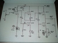
I am trying to design an OTL that will drive ANY impedance cans. My main phones are Audeze LCD-2 CB which are 70 ohms. I also have 32 ohm ohm HE-4xx and 300 ohm HD-650s. I have built four HP amps using Aikido topology, which sound fantastic with 300-600 ohm HP, but not enough oomph for low impedance. I do have 600 ohm OPT but the secondary is only 8 ohms (I was saving them for a 6C33C project). The schematic is attached (preliminary), PS schematic to follow.
Attachments
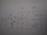
Mistake between V1 and V2… № 2's grid is to have been tapped from № 1's anode, not its grid. Just a drawing mistake, must be.
Looks also like you're trying to use a 'wiggly' constant current cathode drain valve in the last stage. I guess it works. I don't like how such devices tend to have quite a variable VANODE operating point as they age. I'm old, conservatıve, etc.
Other than that, its basically just fine.
You probably should use 2 RED LEDs in series up in the front for Cathode bias.
You also don't really need to have a grid-to-ground pull-down resistor, since the pot up front is also doing the same job.
200 µF on the output … at 20 Hz … is 1/(2πFC) → 40 Ω. Not bad as an in-line impedance bump. Given you're going to hunt down some magic unicorn nonpolar polypropylene caps, well … you'll do just fine.
Other that those things, you're OK.
Double phase inversion restores phase to + → +
⋅-⋅-⋅ Just saying, ⋅-⋅-⋅
⋅-=≡ GoatGuy ✓ ≡=-⋅
Mistake between V1 and V2… № 2's grid is to have been tapped from № 1's anode, not its grid. Just a drawing mistake, must be.
Looks also like you're trying to use a 'wiggly' constant current cathode drain valve in the last stage. I guess it works. I don't like how such devices tend to have quite a variable VANODE operating point as they age. I'm old, conservatıve, etc.
Other than that, its basically just fine.
You probably should use 2 RED LEDs in series up in the front for Cathode bias.
You also don't really need to have a grid-to-ground pull-down resistor, since the pot up front is also doing the same job.
200 µF on the output … at 20 Hz … is 1/(2πFC) → 40 Ω. Not bad as an in-line impedance bump. Given you're going to hunt down some magic unicorn nonpolar polypropylene caps, well … you'll do just fine.
Other that those things, you're OK.
Double phase inversion restores phase to + → +
⋅-⋅-⋅ Just saying, ⋅-⋅-⋅
⋅-=≡ GoatGuy ✓ ≡=-⋅
OOPS, yeah drawing error.
I actually do have PP 200uf film caps (got em for cheap), they are huge!
Last edited:
Do yourself a small favor: on one channel use a 500 µF electrolytic, which is paralleled with a 1 µF “very, very nice” polypropylene. On the other ear, use the Big PP that you already have.
With that in hand, you can do quite a worthy A/B type test, with a pair of DPDT switches.
DPDT allows you to redirect left-to-right-and-vice-versa on the front end. Another DPDT makes sure L and R get to the 'right ear'.
There will not be an annoying POP because you're simply reversing both the connection of both inputs, and both outputs. The capacitors on the output will not be changing their intrinsic DC charge thru the swap.
Ideally, you'd cobble this together in a separate little box. Very valuable to use under all sorts of research and development project stages. Very valuable.
⋅-=≡ GoatGuy ✓ ≡=-⋅
I like that idea. My only reason to use the film caps was because I had them on hand and I have a big chassis to put all this in. The power supply is going to be big because of the highish current demand. I was also thinking of putting the 600 ohm OPT in a separate box that I could switch in and out for speakers.
You will probably find that gain is too high with what you have drawn up. There are lower mu tubes you could use up front that also have lower Gm, so they'll be less fussy about layout.
The 1uF interstage coupling cap is an odd choice unless you have a very specific part in mind that you'd like to use. The grid leak after the 1uF cap would be ~25K or so for decent LF rolloff, but that 25K resistance will defeat the use of the plate choke in the first stage. 0.047uF/500K would be my recommendation for that section.
What you have drawn isn't a White CF, though I don't believe it has to be for what you're looking for. Here's a basic diagram of the White CF from our friend Broskie:

You could simply put a low gain triode ahead of the 6C41 and load the 6C41 with a constant current source or a plate choke as the load. Yes, 32V/180mA is pretty spicy in terms of dissipation, but it's doable.
If we roll all that up into something you could build very easily, it might look like a CCS loaded 12BH7 with maybe 65V on the plate running off a 125V supply and the 6C41 could run off the same supply and be cap coupled to the 12BH7. With the ~25V or so on the cathode of the 6C41 running 100V P-K/180mA IP, you have plenty of compliance to use a CCS. This would get you to ~60 ohms of output impedance. If you wanted to go lower, you could put a little feedback around the amp.
Use the huge poly caps. You have them and they are better off in an amp than sitting in a box somewhere in storage.
The 1uF interstage coupling cap is an odd choice unless you have a very specific part in mind that you'd like to use. The grid leak after the 1uF cap would be ~25K or so for decent LF rolloff, but that 25K resistance will defeat the use of the plate choke in the first stage. 0.047uF/500K would be my recommendation for that section.
What you have drawn isn't a White CF, though I don't believe it has to be for what you're looking for. Here's a basic diagram of the White CF from our friend Broskie:
You could simply put a low gain triode ahead of the 6C41 and load the 6C41 with a constant current source or a plate choke as the load. Yes, 32V/180mA is pretty spicy in terms of dissipation, but it's doable.
If we roll all that up into something you could build very easily, it might look like a CCS loaded 12BH7 with maybe 65V on the plate running off a 125V supply and the 6C41 could run off the same supply and be cap coupled to the 12BH7. With the ~25V or so on the cathode of the 6C41 running 100V P-K/180mA IP, you have plenty of compliance to use a CCS. This would get you to ~60 ohms of output impedance. If you wanted to go lower, you could put a little feedback around the amp.
Use the huge poly caps. You have them and they are better off in an amp than sitting in a box somewhere in storage.
WCF OTL Headphone Amp
As said, V1 done wrong. And the power stage is NOT a White Cathode Follower. In fact it is more a power-sucker.
If it were a WCF: the peak load current could be nearly twice the idle current, which is penciled as 180mA, so over 300mA. My experience and figuring says you can be REALLY LOUD with 150mA peak, and any sane listening happens under 50mA. peak. So this is quite overkill.
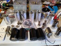
You also want more light on your table.
Attachments
As said, V1 done wrong. And the power stage is NOT a White Cathode Follower. In fact it is more a power-sucker.
If it were a WCF: the peak load current could be nearly twice the idle current, which is penciled as 180mA, so over 300mA. My experience and figuring says you can be REALLY LOUD with 150mA peak, and any sane listening happens under 50mA. peak. So this is quite overkill.
You also want more light on your table.
Would the 6S41S work better in SRPP? Or maybe I can parallel the 6S41S tubes and take the output from the Cathode? I also have some 6C33C tubes that I can use, too, but that would be extremely Overkill.
Yeah the pic is dark; my two year old daughter was napping....you don't want to wake a two year old up early lol
Not particularly.Would the 6S41S work better in SRPP?
That could halve the output impedance, but you'd have to deal with paralleling tubes that are rarely well matched.Or maybe I can parallel the 6S41S tubes and take the output from the Cathode?
I mean, this would work too.I also have some 6C33C tubes that I can use, too, but that would be extremely Overkill.
Do yourself a small favor: on one channel use a 500 µF electrolytic, which is paralleled with a 1 µF “very, very nice” polypropylene. On the other ear, use the Big PP that you already have.
With that in hand, you can do quite a worthy A/B type test, with a pair of DPDT switches.
DPDT allows you to redirect left-to-right-and-vice-versa on the front end. Another DPDT makes sure L and R get to the 'right ear'.
There will not be an annoying POP because you're simply reversing both the connection of both inputs, and both outputs. The capacitors on the output will not be changing their intrinsic DC charge thru the swap.
Ideally, you'd cobble this together in a separate little box. Very valuable to use under all sorts of research and development project stages. Very valuable.
⋅-=≡ GoatGuy ✓ ≡=-⋅
What about the use of russian teflon caps as bypass instead MKP? They are said to be among the best also to be combined with cheap electrolytic caps. Personnally I never used them but I'd be courios...
What about the use of russian teflon caps as bypass instead MKP? They are said to be among the best also to be combined with cheap electrolytic caps. Personnally I never used them but I'd be courios…
Sure, Ruskie teflon is in the “very, very good” class of capacitors. However, as far as the A/C (passing through) is concerned, the remarkably small amount of charge-discharge hysteresis (asymmetry of capacitance as electrons enter or leave a capacitor) on modern polypropylene, teflon and even well-made oiled paper capacitors doesn't really warrant spending a BUNCH of money on magic-unicorn-horn devices. Go cheap, go good, let 'er be.
⋅-⋅-⋅ Just saying, ⋅-⋅-⋅
⋅-=≡ GoatGuy ✓ ≡=-⋅
OK, going to fix the schematic tonight and make it a real WCF and also going to lower the current on the output tubes to 100ma. I'm also going to change V1 to 6N6P.
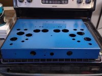
Started planning layout
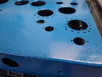
Going dual mono with each side having a hybrid bridge using 6D22S. All toroids and the 6N6P plate choke will be under the chassis. Going to paint it with "Double Blue Vein" powder coat from Prismatic Powders. The chokes and caps will be painted with textured black paint. Going to have dual Alps 100K attenuators for the volume. The output caps are ******* huge! Going to run the 6D22S heaters on series connected 12v toroid (dual secondaries) when all is said and done, will have less than $500 in.
Going dual mono with each side having a hybrid bridge using 6D22S. All toroids and the 6N6P plate choke will be under the chassis. Going to paint it with "Double Blue Vein" powder coat from Prismatic Powders. The chokes and caps will be painted with textured black paint. Going to have dual Alps 100K attenuators for the volume. The output caps are ******* huge! Going to run the 6D22S heaters on series connected 12v toroid (dual secondaries) when all is said and done, will have less than $500 in.
Attachments
Interesting project! 🙂
I have also wanted to build a headphone amplifier that can drive a wide range of headphones. I have been considering both OTL and output transformer solutions. In the end, I went for the latter. It is taking shape at my workbench now.
6S41S are awesome tubes. I have a pair of SE mono blocks with these that sound marvelous.
I look forward to follow your build!
I think I got the final schematic figured out. Going with 6S3P input tube.
It's kinda difficult to see, but the Cathode resistor of 6s41s is 300R @100ma -30v bias
It's kinda difficult to see, but the Cathode resistor of 6s41s is 300R @100ma -30v bias
Attachments
Last edited:
- Home
- Amplifiers
- Tubes / Valves
- 6S41S WCF OTL Headphone Amp