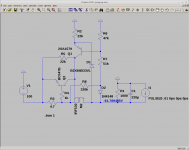
I'am using the bias board from
Module AB-Q for 4 tubes, PP & PPP & Single Ended amps, requires 6.3VAC & bias supply from the amps circuit. Not suitable where the 6.3VAC filament supply is referenced to ground, use the ABF-Q below. ...
for the amp I am building (class AB).
I think its a clone of
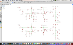
The resistors and output circuit seem to match. The first time I tried it I connected the negative supply straight from the rectifier cap. The result was the bias got modulated by the 50Hz component there causing some modulation. The second time I added a 2k + 470uF to smooth the negative supply. However it takes about 18ma and this was enough to cause all the grid voltages to become too positive. So I settled on 470R. However the circuit seems to offer little rejection of the negative supply.
So I can see the voltage on the grids change if the mains dips (which mine does). Maybe I need to stabilise the negative supply, but I was expecting the grid voltages not to be a function of the supply.
Module AB-Q for 4 tubes, PP & PPP & Single Ended amps, requires 6.3VAC & bias supply from the amps circuit. Not suitable where the 6.3VAC filament supply is referenced to ground, use the ABF-Q below. ...
for the amp I am building (class AB).
I think its a clone of

The resistors and output circuit seem to match. The first time I tried it I connected the negative supply straight from the rectifier cap. The result was the bias got modulated by the 50Hz component there causing some modulation. The second time I added a 2k + 470uF to smooth the negative supply. However it takes about 18ma and this was enough to cause all the grid voltages to become too positive. So I settled on 470R. However the circuit seems to offer little rejection of the negative supply.
So I can see the voltage on the grids change if the mains dips (which mine does). Maybe I need to stabilise the negative supply, but I was expecting the grid voltages not to be a function of the supply.
Sorry for your troubles.
With all that differential gain of those op amps, a very small amount of ground loop hum voltage goes a long way (causes problems).
The problem may be more than just the negative supply ripple.
Now you can see why I use simple circuits.
With all that differential gain of those op amps, a very small amount of ground loop hum voltage goes a long way (causes problems).
The problem may be more than just the negative supply ripple.
Now you can see why I use simple circuits.
Last edited:
Oh it's quite usable I just wondered if there was a quick fix. I does work OK I cannot see any 2'nd harmonic distortion only 3rd (-55dB down at 5W).
I think it get in through Q3/R65 rather than the op-amps.
I think it get in through Q3/R65 rather than the op-amps.
Last edited:
I'am using the bias board from
Module AB-Q for 4 tubes, PP & PPP & Single Ended amps, requires 6.3VAC & bias supply from the amps circuit. Not suitable where the 6.3VAC filament supply is referenced to ground, use the ABF-Q below. ...
for the amp I am building (class AB).
I think its a clone of
View attachment 822633
The resistors and output circuit seem to match. The first time I tried it I connected the negative supply straight from the rectifier cap. The result was the bias got modulated by the 50Hz component there causing some modulation. The second time I added a 2k + 470uF to smooth the negative supply. However it takes about 18ma and this was enough to cause all the grid voltages to become too positive. So I settled on 470R. However the circuit seems to offer little rejection of the negative supply.
So I can see the voltage on the grids change if the mains dips (which mine does). Maybe I need to stabilise the negative supply, but I was expecting the grid voltages not to be a function of the supply.
AB requires about 18 mA current from the BIAS supply. It must be taken into account.
Pavel
Thanks you are the guy from audioamp.eu - many thanks for your help getting it working.
I had a look on ltspice. There may be a quite simple mod. Basically removing the original integrating cap (22uF to ground). Then replacing with an active feedback circuit from the output. The cap needs to scale with the gain (x20) to 1uF but now needs to be 100v so a metal film will do. I need to add a small cap to ground for HF stability and a protection diode. Now if the negative supply changes the op-amp will hold the output at the same voltage. Think that works. I will modify a single channel to check.
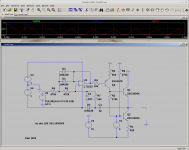
I had a look on ltspice. There may be a quite simple mod. Basically removing the original integrating cap (22uF to ground). Then replacing with an active feedback circuit from the output. The cap needs to scale with the gain (x20) to 1uF but now needs to be 100v so a metal film will do. I need to add a small cap to ground for HF stability and a protection diode. Now if the negative supply changes the op-amp will hold the output at the same voltage. Think that works. I will modify a single channel to check.


Thanks you are the guy from audioamp.eu - many thanks for your help getting it working.
I had a look on ltspice. There may be a quite simple mod. Basically removing the original integrating cap (22uF to ground). Then replacing with an active feedback circuit from the output. The cap needs to scale with the gain (x20) to 1uF but now needs to be 100v so a metal film will do. I need to add a small cap to ground for HF stability and a protection diode. Now if the negative supply changes the op-amp will hold the output at the same voltage. Think that works. I will modify a single channel to check.
View attachment 822832
View attachment 822833
ok
I see you use the HVin pad 🙂
ok
I see you use the HVin pad 🙂
Yep I do but I don't actually need it as the HT supply has a soft start but is up in 10s. I could remove this. I understand it increases the start delay.
but it does not hurtYep I do but I don't actually need it as the HT supply has a soft start but is up in 10s. I could remove this. I understand it increases the start delay.
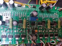
I think I will leave boards as is - its not actually causing any real problem now I have filtered the supply - I don't want to break something as its all working. I could add a negative regulator but don't have much excess voltage to play with. Its just I seem to share the mains supply with the cesspit pump at the bottom of the track where I live.
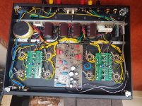

it's ok, I would leave it that wayI think I will leave boards as is - its not actually causing any real problem now I have filtered the supply - I don't want to break something as its all working. I could add a negative regulator but don't have much excess voltage to play with. Its just I seem to share the mains supply with the cesspit pump at the bottom of the track where I live.
View attachment 822842
Who is the designer of the original ?
the principle of function is the same, some circuits are similar, others different.Not sure think I have seen
Vanderveen bias schematic.
- Home
- Amplifiers
- Tubes / Valves
- Servo Bias Boards
