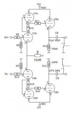
Hi guys, just idea for symmetrical line amp based on famous one which I've found on this forum. May I use is this way please?
Maybe I can do the same with CF at the ouput like with SRPP on input, so use resistor for up and down CF but with 11k value.
Or, do you have any other symmetrical line preamp which you can recommend please?
Thanks.
Maybe I can do the same with CF at the ouput like with SRPP on input, so use resistor for up and down CF but with 11k value.
Or, do you have any other symmetrical line preamp which you can recommend please?
Thanks.
Attachments
That switch will not prevent a Spike from occuring when you connect the preamp output to the power amp.
That is because there is no resistor to ground in the preamp after the coupling cap to get the cap charged (charge the before you set the switch to the power amp).
instead the cap will pass all its charge current through the power amp resistor input.
+POP !
And when you power down the preamp, it will send a negative spike to the power amp when the B+ collapses, hopefully slowly.
- pop !
Depending on how symmetrical your preamp is at turn-on, warm-up, and power down, the effect of the spikes will differ.
The more those changes are truly symmetrical, the more the power amp will reject them as "common mode errors".
But that also depends on how balanced the power amp is.
I would worry about the preamp turn-on, because it will clip the power amp inputs.
1. Put resistors from the coupling caps to ground.
2. Set the switch to disconnect from the power amp.
3. Power on the preamp.
4. Wait for warmup of the preamp tubes, and also the charging of its coupling caps.
5. Then, and only then, set the switch to connect the preamp output to the power amp.
Last edited:
That switch will not prevent a Spike from occuring when you connect the preamp output to the power amp. That is because there is no resistor to ground in the preamp after the coupling cap to get the cap charged (charge the before you set the switch to the power amp). instead the cap will pass all its charge current through the power amp resistor input. POP !
Um… no, I don't think so.
The shunting switch on the output is a 0 Ω resistor, kind of. Thus the output DC blocking capacitor definitely charges up. When it is opened, output terminal is already at ground potential and capacitor has full mean DC charge across it.
Thus, no pop.
Unless of course there's high input analog voltage creating big A/C swings. Then pop is possible.
⋅-⋅-⋅ Just saying, ⋅-⋅-⋅
⋅-=≡ GoatGuy ✓ ≡=-⋅
GoatGuy,
You are correct.
I got caught by mis-reading the international ground symbol.
In fact, it did not register at all on my eye/brain interface.
That caused me to ignore the symbol completely.
I never use that symbol myself, I prefer the other two ground symbols that are (Commonly) used.
However, just forget to set the switch properly, and ALL the charge current will travel through the power amp inputs.
Not to mention a temporary mains power drop out, that causes a hot-start, where the hot filament of the cathode follower can cause the cathode to drive a lot of current to charge the grounded cap if the switch is in the grounded state.
As I often have said: "Grounds Are Commonly Misunderstood"
At work, I typed a sign that said that, and I posted it outside my cubical wall (I retired in 2012 and I believe the sign is still there).
This output is from former schematic, it is not which I want to use. I want to discuss connection as I wrote before.
zdenoeddie,
You want to change R12 and R17 from 22k to 11k?
Depends on the tube you use for cathode follower.
Gain will change slightly.
Distortion will change.
What is the input impedance of the power amp inputs that the preamp drives?
You want to change R12 and R17 from 22k to 11k?
Depends on the tube you use for cathode follower.
Gain will change slightly.
Distortion will change.
What is the input impedance of the power amp inputs that the preamp drives?
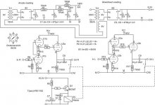
I attach former schematic.
I want to build symmetrical preamp based on attached schematic.
So I put together SRPP part, and I want to know, if it is ok to do it this way. So maybe the same procedure will be fine also for follower on output (use 11k resistor for both sides).
I want to build symmetrical preamp based on attached schematic.
So I put together SRPP part, and I want to know, if it is ok to do it this way. So maybe the same procedure will be fine also for follower on output (use 11k resistor for both sides).
Attachments
Your schematic, Post # 1 has a common cathode resistor for the SRPP stages, that tends to balance the gain.
That is for one channel, not both L and R. You need two such preamps for stereo.
Your schematic, Post # 7 does not have any way to keep the gains of the two circuits the same. You have to select tubes, select resistors, etc.
This is a stereo preamp.
I already discussed about the 22k versus 11k resistor.
You did not give more information as requested in my post # 6.
You will have about 70V at the cathode follower cathode.
22k gives about 3.2 mA.
11k gives about 6.4 mA.
Yes you're right. My goal is to balance the gain, schematic from #1 is for 1 channel as you wrote.
#7 is former schematic for classic asymetrical use.
Regarding #6 - Yes I want to change cathode resistor to half value, because I want to connect it like for SRPP (to balance gain again). So my question is, if this procedure is ok.
Thank you
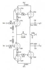
P.S. To clarify it, I attach schematic
#7 is former schematic for classic asymetrical use.
Regarding #6 - Yes I want to change cathode resistor to half value, because I want to connect it like for SRPP (to balance gain again). So my question is, if this procedure is ok.
Thank you
P.S. To clarify it, I attach schematic
Attachments
Last edited:
Huh?
You are going to balance gain by changing cathode resistors from 22k to 11k?
I guess if one side has a little more gain, then you are lowering the resistor from 22k downward a little, and not more downward than 11k?
What kind of gain balance do you have?
What kind of gain balance are you predicting?
Take a look at this link:
stepped balance control for Dynaco SCA35?
and then my post # 28
Last edited:
OK, please look carefully to schematics, in former schematic, there was 22k for each CF on both side. To balance gain for symmetric channel (+ and -), and to preserve working point of tubes, I connect together both sides, and use half of former values. So as you wrote, with 22k through 1 tube is current around 3mA, then, if I put 2 tubes together, there is around 6mA, and to preserve working point, I need half of former value. Clear? 🙂
I want to only know, if this procedure is ok, and I can use it in practical way.
I want to only know, if this procedure is ok, and I can use it in practical way.
No.
Balanced amps and differential amps are one thing (actually two things).
You can not make the gains of your L and R channels equal that way.
But, you will get L + R at one output, and L + R at the other output.
You are making the stereo separation = 0 dB
Not what you want, right?
Balanced amps and differential amps are one thing (actually two things).
You can not make the gains of your L and R channels equal that way.
But, you will get L + R at one output, and L + R at the other output.
You are making the stereo separation = 0 dB
Not what you want, right?
Schematic is for 1 channel + and - side. Other channel will be the same of course. But former schematic is for 2 not symmetrical stereo. So I connect them together to gain one symmetrical channel with auto balance.
...To clarify it, I attach schematic
This plan will not pass any signal. The two sides of the differential signal are SHORTED to each other.
Yes, the DC currents are un-changed. But we do not hear DC. And the resistor under a cathode follower has very little effect on its gain. And in hi-fi systems, or properly differential interconnects, a little asymmetry is not a problem.
Attachments

> How to connect it as symmetrical and with balance?
There are better ways to do it.
Staying with this plan: balance is all down to U1/U3 matching. Common-mode rejection ratio as drawn would be poor; making R9 at least 10 times bigger would be better. (Balancing without CMRR is mostly decorative not beneficial.) The large common cathode resistor will require a large -Negative supply rail. I can't guess how much because I do not know what tube is used.
A negative rail is still needed even with a "CCS", if you actually have adverse ground noise to reject, because the self-bias voltage of most triodes is similar to the amplitude of bad ground noise.
Attachments
I see it. My fault. How to connect it as symmetrical and with balance?
This is complete BS guess. Im sitting here thinking about it, and I am wondering if a hefty pot wouldn't do the job.
Each leg of the pot going to a different cathode, and the wiper going to ground. The job of the cathode resistor in addition to biasing the tube is to prevent your audio from being dumped to ground.
If each half of the pot is acting like its own independent cathode resistor while simultaneously determining how much signal will be shunted to ground, maybe you can use it as a bias/balance control?
It's probably a dumb idea for one reason or another and I am probably just missing something obvious. But hey, maybe it might cause someone to think up an even better solution.
PRR thanks for hint. Tubes are 6n16b, same as in original schematic.
Tjj226, do you have any example of your idea?
Tjj226, do you have any example of your idea?
Sorry, it took me a very long time to determine that what you wanted was a preamp that takes + and - signals in, and gives amplified + and- signals out, that are equal amplitude, but are opposite phase.
You schematic in post # 7 showed both L and R signals, and 6 triodes.
Yes, for stereo, you need 2 preamps (12 triodes total).
You schematic in post # 7 showed both L and R signals, and 6 triodes.
Yes, for stereo, you need 2 preamps (12 triodes total).
Last edited:
It's ok, no problem 🙂
So I try it according PRR recomendations, and we will see. I also find some articles on Tubecad relating to this, so I study them, and hope I will finish it.
So I try it according PRR recomendations, and we will see. I also find some articles on Tubecad relating to this, so I study them, and hope I will finish it.
- Home
- Amplifiers
- Tubes / Valves
- Symmetrical line preamp