You will have to have a lot of capacitance across the resistor that connects from the center tap to ground.
A cap input B+ circuit has very high transient currents, they will appear as voltage transients across the resistor. Just a cap across the resistor will probably not be enough.
A choke input B+ will have smoother current.
In both cases, you likely will have to have at least a 2 pole filter.
Parallel RC from CT to ground.
A second resistor from CT to a second capacitor to ground, take the bias off the second cap.

Unless this is a class A amp, the bias will vary with the music signal. It depends on the momentary B+ load current.
You might get away with a zener instead of that R in the CT, as the zener voltage is more independent of the current through it.
Jan
You might get away with a zener instead of that R in the CT, as the zener voltage is more independent of the current through it.
Jan
For your circuit in post # 3:
You will notice that there is no steady bias voltage until the output tubes draw current.
Well, there is some transient current (and transient bias voltage) when the 2nd and 3rd B+ capacitors are charging, but that is only transient, until the output tube draws current.
I would be very careful of the order of the timing of the rise of the voltages, B+ and Bias.
Do you see that?
You will notice that there is no steady bias voltage until the output tubes draw current.
...You might get away with a zener instead of that R in the CT, as the zener voltage is more independent of the current through it.
Jan
Thank you both for the excellent advice. It’s a stereo preamp so only one tube per channel with output transformer. I didn’t show a second voltage divider on the bias voltage for the other channel. Thinking about what you both wrote, a zener would be better just in case one of the wipers open or a tube is missing etc. Ill be sure to check the time on both the bias and B+
Same circuit, same problem, the timing of the B+ and - Bias voltages.
Partly depends on the load.
Partly depends on the time constants of the B+ and - bias circuits.
You get initial surge current through R111 as diodes in B+ circuit charges C101. Then, you have to wait until there is a full load on B+, before the full -bias is developed from the steady B+ current through R111.
B+ load, is it DHT or slow warming power pentode/beam tetrode?
The load in this cct was PP Class AB1 6V6s. So easily modified to work with other loads. Just need to know what the B+ load is, a solution is easily obtained.
Don't give up yet.😀
Don't give up yet.😀
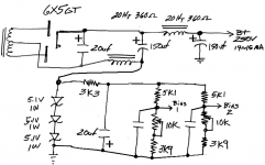
The resistor option did not look that great when I started checking time constants. (Thanks for the tip) Here is a more fleshed out version of zener bias from the center tap (thanks for that tip too) that I think will avoid the problem of the bias lagging the B+ at start up. Any obvious problems with this?
Attachments
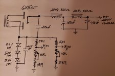
Not sure what the total B+ load current is. Looks like 14~15 mA.
Is that correct? Pls advise, can do a simulation in the morning.
What is the HV each side of CT on the PT?🙂
Is that correct? Pls advise, can do a simulation in the morning.
What is the HV each side of CT on the PT?🙂
There are no vacuum diodes in the Electronic Workbench app so I've stuffed in SS diodes with 100R in series with each to sim the 6X5GT rectifier. A couple of simplifications in the simulation, one 15V Zener rather than three of 5.1V. And one 15K load to replace the two bias columns.🙂
Attachments
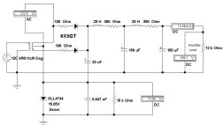
Thanks for checking that. When I sim in Duncan's without the bias scheme I get 265 Vdc out of the filter. I would think you should get more than 189+15. I wonder what I am missing.
The first cap on the +ve side sits on a pedestal of -15V, not a good starting point. I've a couple of ideas, more tomorrow.🙂
I forced myself to figure out how to model it in LT spice. My transformer model is pretty crude but I get the voltages I expected out of the circuit. Running the first filter cap as I show it gets less noise on the bias supply (0.91mV rms) but more complex. I don't have time to figure out the frequencies right now but it looks like line & 4x line or so
So this was not the best idea I ever had. The attached is the simulated output of the bias supply as shown in my last drawing. The shorter period is line x2 and the longer is line/3. Plugging it into the circuit gets 5mV RMS of PS noise on the output of the pre-amp where a pure DC source for bias produces uV levels.
Attachments
> not the best idea
I wondered.
The Zener current is all spikes so the Zener voltage will be all jaggy. 0.05u is not near enough filtering for this low-Z source. But your bias is a fairly hi-Z load. Add a stage of R-C filtering on the bias. Meanwhile take your main B+ filter cap from "common ground", not 3 Vz away.
Some values will need adjustment but this will give you something to try.
Attachments


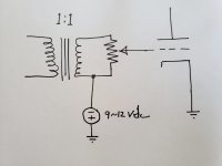
Simply question.
But if you put a little transformer with 0-18 volt at 30-50 mA and the use of a 7915 (just an example) then two trimmer and two resistors you will have a perfect bias regulation.
Of course you need some space but the dimension of the trafo is little.
Walter
But if you put a little transformer with 0-18 volt at 30-50 mA and the use of a 7915 (just an example) then two trimmer and two resistors you will have a perfect bias regulation.
Of course you need some space but the dimension of the trafo is little.
Walter
- Home
- Amplifiers
- Tubes / Valves
- Input transformer negative bias schematic