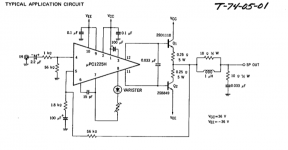
Hello again folks! Im looking to re cap this Yamaha amp and give it to my nephew as a step into this wonderful game of hifi, I have already given him my old celestion 7000 speakers but I gave him a rubbish amp to get started. So my friend put me onto this little amp after reading this review. [Listening test] Yamaha A320 vintage integrated amplifier I really value his opinion and he has heard a lot of gear in his 30 odd years listening to music. He recapped his and gave it a massive thumbs up. Now im only looking to gift this amp on but I would like to ask a few questions and hope for a little information. The amp works so that was a relief as it was sold as "not tested" What I would like to know is whether I should follow the original "typical application" for the main chip and is the Yamaha alternative correct? I know that sounds crazy in my head but it has been known in the past for manufacturers to make mistakes. There are no service manuals available but I believe Yamaha have pretty much just copied the typical circuit all be it with some changes that I will point out.
As you can see in my drawing the amp uses a smaller capacitor on the input and different resister values to ground, it has also added a small ceramic. The thing I find odd is they have put the components in a different order, this is where my lack of understanding circuits comes in. I understand that the values of this input circuit act as a filter, what I would like to know is what affect does the Yamaha version have? At the moment I just plan to change the 1uf Lytic for a 1uf Polyprop. Oh and re cap the rest of the Lytics, to be fair there's not a lot in there, most of the parts being inside that chip. I would also like to know if anyone has any idea how to bias the amp, I would just like to make sure its working at its optimal setting before I hand it over. I can see the pot for adjustment but have no clue what to measure or where? Maybe it is for DC offset and I just need to measure the output?
I really think this is a sleeper, the amp it was built to compete with (Nad 3120) now a classic and therefore commanding much higher prices, I paid £29 on ebay, my friend paid £40. I am thinking polyprops on the input and some mundorf PS caps could sort the not so deep sound stage, time will tell.
Oh and my friend tells me this thing has an excellent phono stage, he built a WAD phono 3 with some expensive components and this is now gathering dust. He did swap out the Black Gates on the Yam and installed some Fine Golds but no mods made to the circuit.
Any ideas comments welcome as always.
Attachments
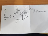
I dunno, it doesn't look overly emotional to me. 😛As you can see in my drawing the amp uses a smaller capacitor on the input and different resister values to ground, it has also added a small ceramic. The thing I find odd is they have put the components in a different order, this is where my lack of understanding circuits comes in. I understand that the values of this input circuit act as a filter, what I would like to know is what affect does the Yamaha version have?
Now as for its effect, looks like Yamaha implemented some input bootstrapping. This is a common sight on amplifiers from this time period. It increases input impedance and, I assume, reduces the negative effect of nonlinear input bias currents along the way - which is of particular importance if the amplifier directly follows a highish-impedance volume pot.
What remains unchanged, of course, is input current noise. You would need some sort of low-noise buffer if that were a problem.
What strikes me as odd is that neither DC resistance nor AC impedance at the driver inputs appear to be balanced particularly well, which is a common approach to keeping DC offset and distortion down. Maybe the former still is plenty low enough and the latter isn't much of an issue due to how small input signal levels are at 40 dB gain... it's literally the input sensitivity spec at most, so probably ~150 mVrms.
These µPC1225s were used for a long time, they can still be found in ca. 2000 Sony surround receivers.
This amp runs 10 dB more gain than what these would normally have been used at, so distortion might not be quite as good as spec. Should still be a decent little amp. I doubt it's an audiophile miracle, but it might still beat the odd misguided boutique construction.
If you were to consider hacking in a buffer stage, I would be tempted to make it not only a buffer but a preamp of about 10-14 dB, reducing gain on the power amp in return and using it as per the application circuit. That would get a bit more involved, however, as you would probably need an opamp rated to +/-18 V abs max, your main supplies are likely to be higher than that and the phonopre supply may not cope with extra loading too well, but it would be doable...
Circuits like this usually don't even have an offset adjustment. It's probably the bias trim. Check whether it's associated with circuitry between pins 7 and 8, that's where a traditional bias spreader would go.I would also like to know if anyone has any idea how to bias the amp, I would just like to make sure its working at its optimal setting before I hand it over. I can see the pot for adjustment but have no clue what to measure or where? Maybe it is for DC offset and I just need to measure the output?
Find the output transistor's pair of emitter resistors, typically 0.22 or 0.33 ohms. Measure DC voltage across either one or both when warm. The region of optimum bias should be reached at ca. 13 mV per resistor (26 mV for both), but factory instructions may call for less if the heatsink is on the small side, so do watch temperature for a while.
Be careful with very large film caps, as they may exhibit enough parasitic capacitance to invite oscillation if placed in a bad spot. Keep away from the output side. Best stick with values small enough to be placed roughly where the original was. (Some people butcher their poor equipment with huge 250-600 V crossover caps, which in general even looks bad. Not a fan.)I am thinking polyprops on the input and some mundorf PS caps could sort the not so deep sound stage, time will tell.
Mundorf make good caps for speaker crossovers, in a power supply there would probably be better candidates for manufacturers - favorites for can-type caps include Epcos/TDK, Kemet, or Nichicon like the originals. A small amp like this may only come with 4700 µF caps stock - a little bump to 6800 or 8200 µF may be worth it.
If there is a protection relay on the output, this may well benefit from cleaning. (Often these have to be unsoldered before they can be opened.) Should the contacts be found to be heavily charred, a matching replacement will have to be found. (If you need a 2x on, often it is easier to buy a DPDT and cut off the two unused pins.) Some people add 10-100 nF across the switch contacts to combat arcing.
Thank you very much for this in depth reply!!! I am working on the amp at the moment and using caps I have to hand, mostly Fine Golds and Muse.
Perfect there is indeed, seems to be working fine after all this time so I will leave that be, I know what to look at if he has issues though. 😉
I dunno, it doesn't look overly emotional to me. 😛
no one is going to cry over this. 😉
Now as for its effect, looks like Yamaha implemented some input bootstrapping. This is a common sight on amplifiers from this time period. It increases input impedance and, I assume, reduces the negative effect of nonlinear input bias currents along the way - which is of particular importance if the amplifier directly follows a highish-impedance volume pot.
Does the fact that they have put the resistors in a different position not matter?
What remains unchanged, of course, is input current noise. You would need some sort of low-noise buffer if that were a problem
I will go on the recommendation that it has no issues in my friends system.
What strikes me as odd is that neither DC resistance nor AC impedance at the driver inputs appear to be balanced particularly well, which is a common approach to keeping DC offset and distortion down. Maybe the former still is plenty low enough and the latter isn't much of an issue due to how small input signal levels are at 40 dB gain... it's literally the input sensitivity spec at most, so probably ~150 mVrm
Maybe not the best amp in the world but not bad for £29?
These µPC1225s were used for a long time, they can still be found in ca. 2000 Sony surround receivers.
Does this make it a bad amp? The TNT review seems to say not.
This amp runs 10 dB more gain than what these would normally have been used at, so distortion might not be quite as good as spec. Should still be a decent little amp. I doubt it's an audiophile miracle, but it might still beat the odd misguided boutique construction.
Well we aren't looking for miracles, just a bargain that sounds great and I think this amp hits that spot?
If you were to consider hacking in a buffer stage, I would be tempted to make it not only a buffer but a preamp of about 10-14 dB, reducing gain on the power amp in return and using it as per the application circuit. That would get a bit more involved, however, as you would probably need an opamp rated to +/-18 V abs max, your main supplies are likely to be higher than that and the phonopre supply may not cope with extra loading too well, but it would be doable...
Oh no I wont be going that far but thanks for the advice, its a step on the ladder for my nephew, its not replacing my Mitchell Alectos. 😀
Circuits like this usually don't even have an offset adjustment. It's probably the bias trim. Check whether it's associated with circuitry between pins 7 and 8, that's where a traditional bias spreader would go.
If you look at the diag I posted it is between 7 and 8 as you say! So its a Bias Spreader....
Find the output transistor's pair of emitter resistors, typically 0.22 or 0.33 ohms. Measure DC voltage across either one or both when warm. The region of optimum bias should be reached at ca. 13 mV per resistor (26 mV for both), but factory instructions may call for less if the heatsink is on the small side, so do watch temperature for a while.
I am going to increase the heat sinks, they are not as big as the product sheet says they should be thanks.
Be careful with very large film caps, as they may exhibit enough parasitic capacitance to invite oscillation if placed in a bad spot. Keep away from the output side. Best stick with values small enough to be placed roughly where the original was. (Some people butcher their poor equipment with huge 250-600 V crossover caps, which in general even looks bad. Not a fan.)
Yes I totally agree, thank you.
Mundorf make good caps for speaker crossovers, in a power supply there would probably be better candidates for manufacturers - favorites for can-type caps include Epcos/TDK, Kemet, or Nichicon like the originals. A small amp like this may only come with 4700 µF caps stock - a little bump to 6800 or 8200 µF may be worth it.
The caps are 6800uf, this is also the biggest I can fit in, I have got an order with mouser ready with Nichicon Audio Grade, half the price of Mundorfs and a good few quid cheaper than the same ones on Hifi Collective. In fact I have all the caps in my basket and the total is £21, this includes the phono stage and they are all Muse/Fine Gold and some Silmic 2's so it isnt going to cost a lot to re cap.
If there is a protection relay on the output, this may well benefit from cleaning. (Often these have to be unsoldered before they can be opened.) Should the contacts be found to be heavily charred, a matching replacement will have to be found. (If you need a 2x on, often it is easier to buy a DPDT and cut off the two unused pins.) Some people add 10-100 nF across the switch contacts to combat arcing.
Perfect there is indeed, seems to be working fine after all this time so I will leave that be, I know what to look at if he has issues though. 😉
Last edited: