Seeing how most pentodes have a square law response from grid 1 in the operating range, just like the Mosfet, (3/2 power law for grid 2) one should be able to use the magnified Mosfet load resistor above a pentode driver tube to linearize it.
A pentode could be used as the magnified load resistor for another pentode too presumably. Similar to the Aikido input stage (usually using triodes).
A magnified Mosfet resistor (lower value) might work in the cathode (degen.) of a tube to linearize its gm.
And for a tube LTP, one could try the magnified Mosfet resistor (a lower value) for the tail resistance to linearize the LTP for large signals (mainly 3rd harmonic).
Last edited:
Hmmm,
putting the magnified (non-linear) resistor in the cathode circuit probably just reinforces the tube's square law behavior, instead of correcting it. Similar to putting a thermionic diode in the cathode circuit. The load side for the nonlinear R looks good though.
putting the magnified (non-linear) resistor in the cathode circuit probably just reinforces the tube's square law behavior, instead of correcting it. Similar to putting a thermionic diode in the cathode circuit. The load side for the nonlinear R looks good though.
Last edited:
A magnified Mosfet resistor (lower value) might work in the cathode (degen.) of a tube to linearize its gm.
Yes, but you need a trick to make the compensating device work in antiphase, otherwise you double the non-linearity.
Here is how it can be done:
It is based on a capacitor bridge C1 C3 and isolating resistors R3 R4.
The transistor version is quite straightforward, because it is acceptable to use a diode-connected transistor as compensator, but with tubes, things are more complex: to make a proper facsimile, you need to operate the correcting tube in the same conditions as the amplifiying tube, meaning in particular a comparable A-K voltage.
This requires a B- voltage equal to B+, not exactly practical.
With the anode load, you just replace a resistor with something else, which is much easier
Attachments

To be constructive, here are some ideas to spice up the circuit.
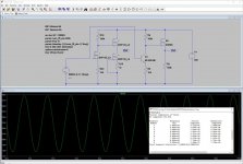
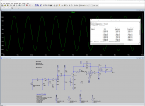
In this voltage amplifier example, the original circuit has a simulated THD of 0.47% with BSP89's as transistors and an output of ~90Vpp:
...
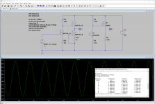
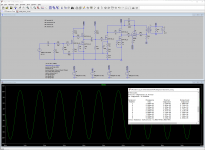
It seems your results are dependent on simulation models. My results are quite different. I used Infineon's spice model for BSP135 and Siemens's model for BF420.
Attachments

Your pics are too small to decipher the figures, but I easily believe you.
In general, a BJT will be much more linear for the reasons I explained, but the BSP135 might have an even higher transconductance, or a completely linear transfer function, or both (in sim at least).
It would be interesting to investigate and pinpoint the origin of the distortion in your circuit.
Note that in the conditions of the sim (which I assume are the same for yours), the real circuit built by Jack with BSP135's yielded 0.83% THD, twice the simmed value with BSP89 (which means nothing).
I do not know what your figures are, but the BJT variant should be much better than that, even if it doesn't arrive at 0.038%
Your pics are too small to decipher the figures, but I easily believe you.
In general, a BJT will be much more linear for the reasons I explained, but the BSP135 might have an even higher transconductance, or a completely linear transfer function, or both (in sim at least).
It would be interesting to investigate and pinpoint the origin of the distortion in your circuit.
Note that in the conditions of the sim (which I assume are the same for yours), the real circuit built by Jack with BSP135's yielded 0.83% THD, twice the simmed value with BSP89 (which means nothing).
I do not know what your figures are, but the BJT variant should be much better than that, even if it doesn't arrive at 0.038%
Here are the same pictures in a larger format. By adjusting the DC bias the THD in Menno Cell can be lowered to 0.09%. The same applies to the BJT variant as well. With the models I'm using the BJT variant reached 0.01% THD when the DC bias was 3V.
Attachments
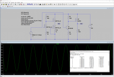
I cannot explain why the Siemens BF420 model performs so much worse than the Philips one: it should be the opposite, because the Philips has a much lower Vaf.
Anyway, 0.09% with the BSP135 is pye in the sky compared to the 0.83% of the reality.
There are probably compensation mechanisms leading to the (apparent) cancellation of some distortions
Anyway, 0.09% with the BSP135 is pye in the sky compared to the 0.83% of the reality.
There are probably compensation mechanisms leading to the (apparent) cancellation of some distortions
I cannot explain why the Siemens BF420 model performs so much worse than the Philips one: it should be the opposite, because the Philips has a much lower Vaf.
Anyway, 0.09% with the BSP135 is pye in the sky compared to the 0.83% of the reality.
There are probably compensation mechanisms leading to the (apparent) cancellation of some distortions
Yes, simulations are just simulations, dependent on models and typically overly optimistic. Simulations of tube power amps often fail to model the output transformer which I have found out to be the most critical part. Gobs of feedback can hide output transformer deficiencies in simulations but not in practice. And in some cases intrinsic distortion cancellations between tube stages may be missed in simulations. I do not know if this type of distortion cancelling is occurring with Menno amp. Anyhow simulating the whole Menno amp predicts that it has quite low THD which is to be expected due to the amount of feedback used. I used E130L as the output tube since I have worked with that before.
Based on the article I would assume that the primary goal of the Menno-Cell was not to have the lowest THD but to be a universal building block similar to tubes. E.g. the CCS in Menno-Cell offers few benefits and can be replaced with a suitable resistor. Using CCS however makes it more immune to operating points etc. which may be more important for generic use. Also the use of depletion mosfets instead of bjts may be due to the same goal.
Here is one way to deploy "Elvee-cell" in Menno's amp. I replaced the preamp Menno-cell with 12AT7.
Attachments
I know that one goal of Menno was to have a low impedance point driving the output transformer, so that it (the xformer) would distort very little. That avoids the complexity of overall feedback from the secondary with the xformer phase shift.
Jan
Jan
In the context of a regular tube amp the differences between the Menno cell and the other amplifier variant (no need to call it Elvee cell) even out, because they are drowned in the THD generated by the tubes and the transformer.Based on the article I would assume that the primary goal of the Menno-Cell was not to have the lowest THD but to be a universal building block similar to tubes. E.g. the CCS in Menno-Cell offers few benefits and can be replaced with a suitable resistor. Using CCS however makes it more immune to operating points etc. which may be more important for generic use. Also the use of depletion mosfets instead of bjts may be due to the same goal.
Here is one way to deploy "Elvee-cell" in Menno's amp. I replaced the preamp Menno-cell with 12AT7.
Anyway, having a simpler and more effective circuit is not to be scorned at, even if the advantage is small
It seems like you'd want a circuit in the second cell position that does a very linear V-to-I conversion. Does the cell do that well?
I've been playing around with similar amp topologies for some time and for my next experiment I was thinking of building a stage to drive the feedback resistor/output grid that mimicked the input stage of a solid-state amp. Differential stage with CCS tail and current mirror load. I think that would do the job of linear V-to-I converter pretty well, and you'd get an output stage with nearly 100% local feedback so very low distortion and low Zout. Also, you'd have a very convenient point to attach feedback from the OT secondary if desired.
I've been playing around with similar amp topologies for some time and for my next experiment I was thinking of building a stage to drive the feedback resistor/output grid that mimicked the input stage of a solid-state amp. Differential stage with CCS tail and current mirror load. I think that would do the job of linear V-to-I converter pretty well, and you'd get an output stage with nearly 100% local feedback so very low distortion and low Zout. Also, you'd have a very convenient point to attach feedback from the OT secondary if desired.
A pentode (LTP/CCS) should work well for a current output driver for the "shunt Schade" N Fdbk. It just gets into a some extra tubes if you are going to do one LTP per output tube in P-P. But once you have gone to the length of that, then other variations are available as well to experiment.
You could use the LTP N Fdbk to do a triode emulation (aka super-triode) scheme. Making each output tube act like a high power triode. If the LTP tubes have good internal triode characteristics themselves, you could take the UL taps (attenuated) back to the driver screen grids (ie, differential driver UL) for a similar effect.
12HL7 (selected) have good internal triode characteristics. 4P1L, 6197, 6LQ8 too. And many others.
Attachments
Last edited:
A pentode (LTP/CCS) should work well for a current output driver for the "shunt Schade" N Fdbk. It just gets into a some extra tubes if you are going to do one LTP per output tube in P-P. But once you have gone to the length of that, then other variations are available as well to experiment.
Some time back I bought a pair of SE transformers so I was going to make one SE amp. I was thinking one 6BN11 to drive each output tube.
Tying this back to the thread, I'd think that a small board with a differential mosfet pair V-to-I converter for the second "cell" would result in a measurable increase in performance. Of course, then you'd have to have two board designs, etc.
The high gm of the Mosfet scales with current. Both Mosfet and a tube grid 1 are approx. square law. If you put the -same- current through a Mosfet or a 12HL7, the Mosfet has about a 10:1 gm advantage. A much higher ratio develops versus non frame grid tubes of course. All depends on how linear the output tubes are as to how much gm is needed in the driver to fix them.
4P1L and 6197 are quite linear even in pentode mode, if low power (7.5 W tubes) is acceptable. Both tube types (the GE 6197 at least) are quite consistent for paralleling. Bigger tubes generally have "Crazy drive" available.
Another option would be "active UL". Use an Op Amp (or tube LTP) to control the grid2 V for linear output versus grid 1 V.
Attachments


Showing my inexperience here, just dipping a toe into the bath water of valve circuits....
Has anyone just used a BJT for the cathode circuit, a la Rubber Diode/Amplified Diode circuit?
Has anyone just used a BJT for the cathode circuit, a la Rubber Diode/Amplified Diode circuit?
If you mean use a BJT for a current source in a coupled cathode phase splitter, yes.
Otherwise, please draw a schematic of what you are talking about.
Otherwise, please draw a schematic of what you are talking about.
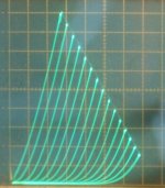
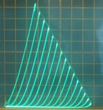
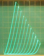
Just to be clear, I'm not talking about using a differential stage as a phase splitter, I'm talking about using it to linearize the pentode which has to work into a vertical load as a V-to-I converter. It is not hard to see the uneven spacing of the curves of even the most linear pentodes working into a near vertical load.
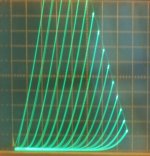
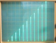
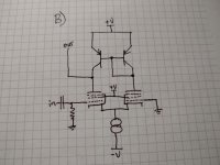
The idea is to set up a circuit to use two pentodes to work in a way that one pentode is working upward into its steep load while the other is working downward so that the composite characteristic of the circuit has more evenly spaced curves. It's not an idea I came up with, it's a copy of your standard solid-state audio amp input stage.
It is wasteful because it uses two tubes for a single phase of a V-to-I conversion (or two mosfets if we are making a little board to do the job) but I'm guessing it would be measurably better in an amp like Menno's.
I haven't had the chance to get to this line of experimenting to prove the superiority of one over the other, but that's where I want to go next.
Attachments
A simple pair of triodes with a current source in the coupled cathodes (direct connected cathodes), and with nothing more than resistive plate loads, only one triode driven, and one triode grid grounded, will reduce the 2nd harmonic distortion of the driven triode.
You just take the output off the one triode plate, and not use the inverted side plate.
And if you do use both plate signals as an invertor, both of them have reduced 2nd harmonic distortion versus a single triode at the same voltages, current, a bypassed cathode, and the same same plate load.
I expect that using a pair of pentodes in the same configuration would also reduce the 2nd harmonic of the driven pentode, and again, you do not use the un-driven pentode output (unless you want that signal, which also has reduced 2nd harmonic distortion versus a single pentode).
Someone else will have to tell us how to change the circuit to make it a V to I convertor (a resistive plate load makes it a V to V circuit), and then what happens to the performance when it is configured as a V to I convertor. But I bet if you do that, then the 2nd harmonic distortion will be reduced.
Sorry, but it does not answer your question.
By the way, I never did like to have current sources in both the bottom and the top of a circuit, not single ended, not differential or invertor . . . very tricky.
The only good way to do that is to set one current source to slightly less current than the other current source, and then put a resistor across the lesser current source to 'suck up' the excess current from the greater current source. And now, the lesser current source becomes a high resistance imperfect current source.
Making two independent current sources have exactly the same current over changing voltages and changing temperature is like a dog chasing its tail.
Last edited:
- Home
- Amplifiers
- Tubes / Valves
- The "Menno Cell" - Trans Technology