Been experimenting with using REW as a linear phase FIR generator.
Basic idea is to use a measurement's inverse impulse response as the mag and phase correction. And then add a xover to that inverse.
So apart from a measurement, all that is needed are a couple of imports from rephase, a Dirac pulse (flat mag and phase trace) and the chosen xover.
It takes 3 steps of trace arithmetic, and then applying IR Windowing to the final FIR file.
I just posted a thread on the REW forum asking John M for further guidance...it outlines the steps and has a mdat that's the source of attachments below.
REW as FIR maker | AV NIRVANA
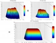
Anyway, first below is the lower HF section of my well known 4594he coax CD on xt1464. Measurement, inverse with xover, then result on same page.
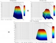
The second is the VHF section.
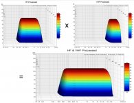
The third is processed HF and VHF sections stitched together.
I thought I'd show water falls cause they are less boring than mag and phase traces and they are prettier 😀
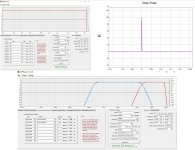
The last is the Dirac pulse and xovers needed from rephase (so folks can see how simple they are to generate.)
All the waterfalls are actual measurements, albeit electrical only.
I turned the actual measurement into a FIR file and put it in series with correction FIR file to get the final pretty outputs.
But if anyone is wondering, it works acoustically just as well, at least to a spot.
Same driver and horn, same process, acoustic results are here...https://www.diyaudio.com/forums/mul...g-horn-reflections-throat-16.html#post6027639
It's what has me on this REW process kick. Big thx again to nc535 for coming up with how to IR window for export as FIR.
I'm currently exploring how well it works for using REW FIR in IIR mode, without any latency...looking promising so far🙂
One big caveat/warning...if you try this make sure you have a xover in place with the inverse, otherwise out of band amplitude can be destructive.
Same thing for "full range". Put some kind of high pass in till you're sure all is well.
Does anybody know a txt or wav, to bin converter?
Would like to try this with a minidsp unit also...
Basic idea is to use a measurement's inverse impulse response as the mag and phase correction. And then add a xover to that inverse.
So apart from a measurement, all that is needed are a couple of imports from rephase, a Dirac pulse (flat mag and phase trace) and the chosen xover.
It takes 3 steps of trace arithmetic, and then applying IR Windowing to the final FIR file.
I just posted a thread on the REW forum asking John M for further guidance...it outlines the steps and has a mdat that's the source of attachments below.
REW as FIR maker | AV NIRVANA
Anyway, first below is the lower HF section of my well known 4594he coax CD on xt1464. Measurement, inverse with xover, then result on same page.
The second is the VHF section.
The third is processed HF and VHF sections stitched together.
I thought I'd show water falls cause they are less boring than mag and phase traces and they are prettier 😀
The last is the Dirac pulse and xovers needed from rephase (so folks can see how simple they are to generate.)
All the waterfalls are actual measurements, albeit electrical only.
I turned the actual measurement into a FIR file and put it in series with correction FIR file to get the final pretty outputs.
But if anyone is wondering, it works acoustically just as well, at least to a spot.
Same driver and horn, same process, acoustic results are here...https://www.diyaudio.com/forums/mul...g-horn-reflections-throat-16.html#post6027639
It's what has me on this REW process kick. Big thx again to nc535 for coming up with how to IR window for export as FIR.
I'm currently exploring how well it works for using REW FIR in IIR mode, without any latency...looking promising so far🙂
One big caveat/warning...if you try this make sure you have a xover in place with the inverse, otherwise out of band amplitude can be destructive.
Same thing for "full range". Put some kind of high pass in till you're sure all is well.
Does anybody know a txt or wav, to bin converter?
Would like to try this with a minidsp unit also...
Attachments
Last edited:
The bin file is raw 32bit float mono. Export the IR from REW as 32bit wav open in Audacity and export as raw 32 bit float, then change the extension to bin from raw. Should work. That is part of what I was doing with Halair's files.Does anybody know a txt or wav, to bin converter?
Would like to try this with a minidsp unit also...
DRC can do the txt to wav conversion and set the exact number of taps you want and outputs as 32bit float pcm, just change the extension to bin, that was how I made the last file I sent to you to try that worked as expected.
That is the one downside to REW's windowing for tap reduction it is not exact as you only go to the nearest millisecond not the exact sample.
I haven't read the rest of what you have been doing enough to comment 🙂

Thx fluid
Been trying the Audacity conversion you describe. No luck yet.
When I export from REW, a 86ms wave 32 bit float (4128 taps at 48kHz),
it shows up as trying to load 65,556 taps into openDRC after the Audacity conversion.
And I found out i was full of crapola thinking I could move IR Window export to 0-1ms to replicate IIR easily.....it might still work, but right now my mellon is tied up in circles LoL.
One thing i do know is how well the process works for automatic EQ and linear phase correction.
It's so dang simple !
a. Take measurement in REW
b. import dirac pulse and xover from rephase
c. divide dirac pulse by measurement (A/B) to get impulse inverse
d. multiply c. by xover
e. apply IR Window to d. Equal left and right window times.
f. export impulse as wav or txt, = FIR file for processor
g. enjoy near perfect correction
And what really has me going, is that REW allows FDW to be applied to the FIR file export. Simple cure for over correction.
Also allows EQ's to be added to export for house curves, fine tuning after measurement etc.
Damn powerful and easy imo, and at a great price compared to automated commercial alternatives 🙂
VCAD is able to the same + bin export for miniDSP but it's not REW and rePhase so obviously off-topic. Sorry.
This is Scan-Speak 12MU, 200Hz to 4kHz LR4 linear-phase:
This is Scan-Speak 12MU, 200Hz to 4kHz LR4 linear-phase:
An externally hosted image should be here but it was not working when we last tested it.
Send me through the file and I will see if I can work out what is going wrong.Thx fluid
Been trying the Audacity conversion you describe. No luck yet.
When I export from REW, a 86ms wave 32 bit float (4128 taps at 48kHz),
it shows up as trying to load 65,556 taps into openDRC after the Audacity conversion.
You can cut the IR in Audacity to place the impulse peak at the first sample if that is what you want.And I found out i was full of crapola thinking I could move IR Window export to 0-1ms to replicate IIR easily.....it might still work, but right now my mellon is tied up in circles LoL.
You can skip b and c if you use the 1/A (or 1/B just depends which slot your measurement is in) function in REW, gets to the same result 🙂a. Take measurement in REW
b. import dirac pulse and xover from rephase
c. divide dirac pulse by measurement (A/B) to get impulse inverse
d. multiply c. by xover
e. apply IR Window to d. Equal left and right window times.
f. export impulse as wav or txt, = FIR file for processor
So VituixCAD has an inverse function?VCAD is able to the same + bin export for miniDSP but it's not REW and rePhase so obviously off-topic. Sorry.
This is Scan-Speak 12MU, 200Hz to 4kHz LR4 linear-phase:
Does the MiniDSP expect the data to have any specific byte order when it is importing the coefficients? I have been trying to transfer some other files to make them work as bin files and ran into a few weird effects going from a self describing format to raw data.
Where does the 3K ridge come from in the waterfall in your first post?
What filter did you use to rolloff the VHF boost shown in the red rephase trace?
What filter did you use to rolloff the VHF boost shown in the red rephase trace?
VCAD is able to the same + bin export for miniDSP but it's not REW and rePhase so obviously off-topic. Sorry.
Thanks kimmosto, not off topic at all.
I'm interested in any easy to use, economical, semi-automated FIR generator.
Didn't know VCAD could import measurements till now.
VCAD does so much it's almost daunting for an old make sawdust and measure kinda guy like me 😱 🙂
Send me through the file and I will see if I can work out what is going wrong.
You can cut the IR in Audacity to place the impulse peak at the first sample if that is what you want.
You can skip b and c if you use the 1/A (or 1/B just depends which slot your measurement is in) function in REW, gets to the same result 🙂
Will send file, thx 🙂
And I'll look at cutting the IR in Audacity.
I found I could not skip b and c.
1/A (measurement being A) gives different results than imported-dirac/A.
Been meaning to investigate why....
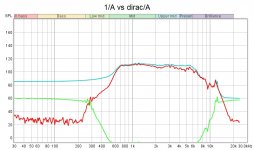
Ok edit....just looked at 1/A vs dirac/A.
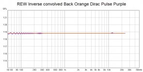
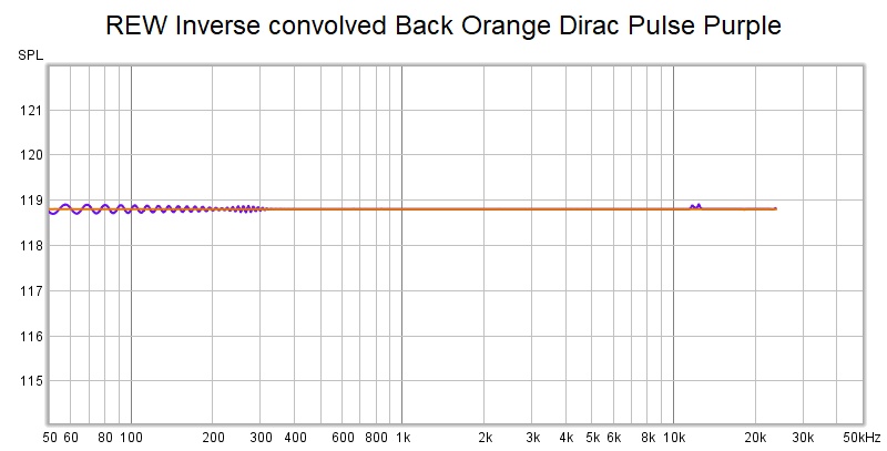
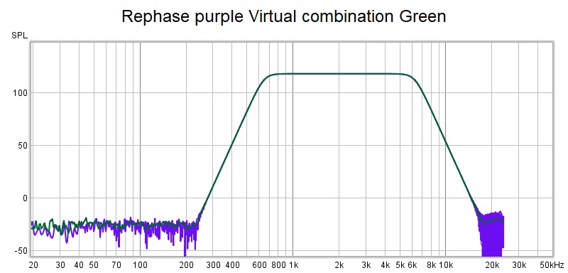
Both look the same as per green trace below. But only the dirac keeps working after xover.
The dirac import is 4124 taps with impulse centering. It gives the red trace that, after multipied by green, is the FIR filter after export.
1/A gives the blue trace and is no good.
Attachments
Last edited:
Where does the 3K ridge come from in the waterfall in your first post?
What filter did you use to rolloff the VHF boost shown in the red rephase trace?
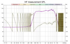
The 3K is from the HF section raw measurement as below
It's really at about 2.3K....i think I'll start using a 0 degree waterfall perspective, to keep from skewing the reading of the response curve.
Not following what you mean by VHF boost.... the red rephase trace is the VHF xover that the VHF inverse is multiplied by.
(I just put both xovers on the rephase trace for brevity...)
Attachments
Send me an mdat with the driver and crossover traces in and I will see if I get the same result if you likeWill send file, thx 🙂
1/A (measurement being A) gives different results than imported-dirac/A.
Been meaning to investigate why....
Ok edit....just looked at 1/A vs dirac/A.
Both look the same as per green trace below. But only the dirac keeps working after xover.
The dirac import is 4124 taps with impulse centering. It gives the red trace that, after multipied by green, is the FIR filter after export.
1/A gives the blue trace and is no good.
I don't see anything in that measurement that would ring at one frequency for so long as shown in the waterfall, maybe just a setting problem as it doesn't appear in the final one.The 3K is from the HF section raw measurement as below
It's really at about 2.3K....i think I'll start using a 0 degree waterfall perspective, to keep from skewing the reading of the response curve.
Not following what you mean by VHF boost.... the red rephase trace is the VHF xover that the VHF inverse is multiplied by.
(I just put both xovers on the rephase trace for brevity...)
I meant what filter did you use at the right hand side of the red rephase graph. That would stop any excess high frequency boost from the inversion stage.
I meant what filter did you use at the right hand side of the red rephase graph. That would stop any excess high frequency boost from the inversion stage.
Aah, that's a LR384 dB/oct low pass at 19.5kHz.
Will send mdat
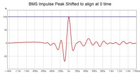
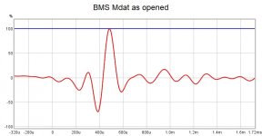
I see the reason why the 1/A is not working for you. The impulse peak of the BMS driver needs to be at time 0, REW will select the first negative peak when in fact you want the first positive peak. I have moved it manually and this is what the impulse looks like when you do that.

The Inverse then works as expected and is actually better than your Dirac pulse original when zoomed in, if all are aligned correctly there should be no difference
Here is the difference

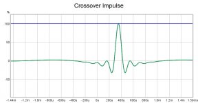
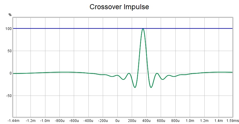
Your crossover impulse was not aligned to 0 either

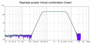
I generated my own impulses to ensure time alignment this is the difference between the textbook example and the virtual measured one when you align all the impulses

When doing these kinds of virtual combinations you have to have the impulses aligned the same or you might not get the correct result. Real life is a bit more forgiving than trace arithmetic though 🙂
The Inverse then works as expected and is actually better than your Dirac pulse original when zoomed in, if all are aligned correctly there should be no difference
Here is the difference
Your crossover impulse was not aligned to 0 either
I generated my own impulses to ensure time alignment this is the difference between the textbook example and the virtual measured one when you align all the impulses
When doing these kinds of virtual combinations you have to have the impulses aligned the same or you might not get the correct result. Real life is a bit more forgiving than trace arithmetic though 🙂
Attachments
not off topic at all.
Ok. I just added new export to rev. 2.0.36.0: FIR transfer function for Driver i.e. driver's linear-phase target response divided by raw response to reference angle. This helps creating transfer function files for TF blocks without Calculator.
Add drivers, load measured+merged responses, create target curves with Optimizer and export FIR-FT files.
Add Transfer function block and buffer for each driver in XO and load exported FIR-TF files. Export IR files for FIR convolver with Impulse response window.
Last edited:
I see the reason why the 1/A is not working for you. The impulse peak of the BMS driver needs to be at time 0, REW will select the first negative peak when in fact you want the first positive peak. I have moved it manually and this is what the impulse looks like when you do that.

The Inverse then works as expected and is actually better than your Dirac pulse original when zoomed in, if all are aligned correctly there should be no difference
Here is the difference
Your crossover impulse was not aligned to 0 either
I generated my own impulses to ensure time alignment this is the difference between the textbook example and the virtual measured one when you align all the impulses
When doing these kinds of virtual combinations you have to have the impulses aligned the same or you might not get the correct result. Real life is a bit more forgiving than trace arithmetic though 🙂
Hi fluid, something seems amiss.
When i open the mdat i sent you, it shows the measurement, the dirac, and the xover all having positive impulse peak at t=0.
And I have 'For Imports Set t=0 at impulse peak' under Preference: Analysis.
So dunno why you're seeing timing offsets ????
Before I jump to what I've been seeing/trying, i need to follow what you did in your last post...because so far I can't replicate it, as simple as it appears.
My gathering is you:
a. made sure meas and xover positive peaks were at t=0
b. 1/A for measurement inverse
c. multiplied by xover
Correct? Did you change the impulse timing of 1/A before multiplying by xover?
Your process looks great...
I've tried various impulse alignments before applying trace arithmetic,
Time Align, which appears to be the same as Estimated IR delay shift applied.
Align IR Start (which makes the most visual sense to me in terms of picturing time alignment.)
And setting positive impulse peak to t=0.
All three have worked under the cascaded dual FFT test, but the Align IR Start has given the closest to perfect results with no more than a sample or two of time delay needed to sum the HF and VHF sections.
(I should add 'Align IR Start' needs 'Apply Windows, Keep Reference Time' when using IR Windows.)
The exact step by step is here REW as FIR maker | AV NIRVANA
I was hoping to get a reply for a better process, but in fairness to John, I know I'm off the intended REW use path.
Your help is most welcome....
Cause REW makes timing toooooo stinkin complicated imo.
Estimated IR delay gives one timing, IR Start Align another, and then there's Set Peak at t=0...and oh, we haven't even got to generate minimum phase.
If someone could provide a clear distinction between these timings...wow, what a help that would be 🙂 Sorry for the rant 😱
Ok. I just added new export to rev. 2.0.36.0: FIR transfer function for Driver i.e. driver's linear-phase target response divided by raw response to reference angle. This helps creating transfer function files for TF blocks without Calculator.
Add drivers, load measured+merged responses, create target curves with Optimizer and export FIR-FT files.
Add Transfer function block and buffer for each driver in XO and load exported FIR-TF files. Export IR files for FIR convolver with Impulse response window.
Very nice kimmosto, thanks !
I'm going to begin digging into VCAD immediately.
Had shoulder surgery for accumulated sports injuries and am confined to desk duty for a month or so.
That's why/how I'm finally trying to get to bottom of REW's measurements and trace arithmetic capabilities. VCAD makes a great next learning project..
I have the same preference set but when opening an mdat you are not importing it, that is for importing impulse responses directly.Hi fluid, something seems amiss.
When i open the mdat i sent you, it shows the measurement, the dirac, and the xover all having positive impulse peak at t=0.
And I have 'For Imports Set t=0 at impulse peak' under Preference: Analysis.
So dunno why you're seeing timing offsets ????
If you do have the impulses with positive peaks at t=0 then check that the ref mark is also at 0.
If they are all aligned correctly then combining them should give correct results.
Yes that is what I did, I manually moved the peak of the bms measurement so the positive peak was at t=0, REW's estimate IR delay put the first negative peak at 0 which is what initially made the convolutions give unexpected results.Before I jump to what I've been seeing/trying, i need to follow what you did in your last post...because so far I can't replicate it, as simple as it appears.
My gathering is you:
a. made sure meas and xover positive peaks were at t=0
b. 1/A for measurement inverse
c. multiplied by xover
Correct? Did you change the impulse timing of 1/A before multiplying by xover?
Your process looks great...
I made my own version of your crossover in rephase and imported that so the peak was already at 0.
The 1/A was done on the measurement after the timing was changed. I did not change the timing of the inverse but oddly the peak was put negative 100ms from the measurement but the reference point was set to the peak so the combination worked as expected.
If the inverse function is working multiplying the inverse by the original will give you a flat line which is what I got when I aligned all the peaks, combining the inverse with the crossover and then multiplying that by the original should give you the crossover shape with a slightly different noise floor. If you don't get that then timing is wrong somewhere.
The reason I bought it up is because you said the inverse function gave a different result to a dirac pulse division. That can only be because of a timing mismatch or a bad pulse, your pulse was as a good as it's possible to make so that wasn't the issue.
I have tried all of the automatic settings for aligning IR's and have found the only way to be sure is to do it manually. I have done a lot of vector averages and time align works pretty well for those but it is not always correct so if ultimate accuracy is needed then manual alignment by using the arrow keys will get you there it just takes time and effort.I've tried various impulse alignments before applying trace arithmetic,
Time Align, which appears to be the same as Estimated IR delay shift applied.
Align IR Start (which makes the most visual sense to me in terms of picturing time alignment.)
And setting positive impulse peak to t=0.
All three have worked under the cascaded dual FFT test, but the Align IR Start has given the closest to perfect results with no more than a sample or two of time delay needed to sum the HF and VHF sections.
(I should add 'Align IR Start' needs 'Apply Windows, Keep Reference Time' when using IR Windows.)
The exact step by step is here REW as FIR maker | AV NIRVANA
I was hoping to get a reply for a better process, but in fairness to John, I know I'm off the intended REW use path.
Your help is most welcome....
Cause REW makes timing toooooo stinkin complicated imo.
Estimated IR delay gives one timing, IR Start Align another, and then there's Set Peak at t=0...and oh, we haven't even got to generate minimum phase.
If someone could provide a clear distinction between these timings...wow, what a help that would be 🙂 Sorry for the rant 😱
For minimum phase follow John's advice in the other thread generate minimum phase version from the all spl measurement actions tab. Export that with your windows set as you want.
I have the same preference set but when opening an mdat you are not importing it, that is for importing impulse responses directly.
If you do have the impulses with positive peaks at t=0 then check that the ref mark is also at 0.
If they are all aligned correctly then combining them should give correct results.
Yes that is what I did, I manually moved the peak of the bms measurement so the positive peak was at t=0, REW's estimate IR delay put the first negative peak at 0 which is what initially made the convolutions give unexpected results.
I made my own version of your crossover in rephase and imported that so the peak was already at 0.
The 1/A was done on the measurement after the timing was changed. I did not change the timing of the inverse but oddly the peak was put negative 100ms from the measurement but the reference point was set to the peak so the combination worked as expected.
If the inverse function is working multiplying the inverse by the original will give you a flat line which is what I got when I aligned all the peaks, combining the inverse with the crossover and then multiplying that by the original should give you the crossover shape with a slightly different noise floor. If you don't get that then timing is wrong somewhere.
The reason I bought it up is because you said the inverse function gave a different result to a dirac pulse division. That can only be because of a timing mismatch or a bad pulse, your pulse was as a good as it's possible to make so that wasn't the issue.
I have tried all of the automatic settings for aligning IR's and have found the only way to be sure is to do it manually. I have done a lot of vector averages and time align works pretty well for those but it is not always correct so if ultimate accuracy is needed then manual alignment by using the arrow keys will get you there it just takes time and effort.
For minimum phase follow John's advice in the other thread generate minimum phase version from the all spl measurement actions tab. Export that with your windows set as you want.
All you say makes sense and matches my understandings.
I'm aware of the timing difference in opening an mdat with a previous measurement, and importing an impulse.
Fortunately REW keeps us informed which is which, on the Measurement info panel.
Check out the mdat i sent and you'll see the measurement was an import and impulse was at t=0. If it's not at t=0 it's been shifted around by actions.
One huge difficulty i've found, is once i shift an impulse, and try to shift again, or apply different IR windows, is that after one shift all bets appear to be off.
I just start completely over with every different alignment attempt.
I've come to the conclusion 1/A inverse must have a bug, or I'm missing something fundamental. REW V5.20 Beta 37
To help get to the bottom of why I get good inverse results with dirac / meas, and not with 1 / meas, I simplified the test platform and am now using a single TC9 on a 6" wide baffle.
I'm applying the FIR correction filter with xover and then making acoustical measurements to eliminate any potential cascaded FIR filter complexities.
So simple easy peasy now.
And both methods; setting all impulses at t=0, or using Align IR Start, prior to trace arithmetic, give near perfect REW results.
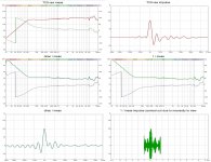
Below is the TC9's raw SPL and impulse traces.
Middle row is the inverses. Dirac / meas, and 1/ meas.
And third row is the inverses' impulses.
As you can see, the two inverses have identical looking mag and phase curves.
But look at the dang impulse difference!
And since the 1/A inverse is from a meas set t=0 at peak, I can't see how the whacked out impulse can be due to anything other than a bug. or again, me totally missing something. I've tried IR start, Est IR delay, etc...all whacked impulses...
I Dunno what's a happening , .......obviously 🙄
Attachments
All you say makes sense and matches my understandings.
Check out the mdat i sent and you'll see the measurement was an import and impulse was at t=0. If it's not at t=0 it's been shifted around by actions.
I've come to the conclusion 1/A inverse must have a bug, or I'm missing something fundamental. REW V5.20 Beta 37
To help get to the bottom of why I get good inverse results with dirac / meas, and not with 1 / meas, I simplified the test platform and am now using a single TC9 on a 6" wide baffle.
I'm applying the FIR correction filter with xover and then making acoustical measurements to eliminate any potential cascaded FIR filter complexities.
As you can see, the two inverses have identical looking mag and phase curves.
But look at the dang impulse difference!
And since the 1/A inverse is from a meas set t=0 at peak, I can't see how the whacked out impulse can be due to anything other than a bug. or again, me totally missing something. I've tried IR start, Est IR delay, etc...all whacked impulses...
I Dunno what's a happening , .......obviously 🙄
There is something happening and my only conclusion is that somehow there is a timing issue. By using your data and moving the positive peaks of the impulses to 0 I get the expected result as shown in the graphs previously, and you get the same with the TC9.
These are shots taken from the mdat when first opened to show how they display for me, at this point I have not touched them, if this is not how they look for you I can't explain why.
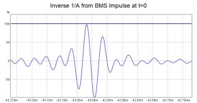
This is a zoomed version of the 1/A impulse when timing is correct, which is a good match for your 43ms window time
The mag and phase trace for the dirac vs inverse are not the same, there is an obvious difference between the two visually, the 1/A is a more accurate inverse as seen most readily by the phase trace below 100Hz. Your TC9 measurement is very clean there, the dirac is not quite as good. But having said that the practical difference is nothing to worry about.
I don't think this is a bug it is just showing the truth which isn't so pretty, the dirac pulse is necessarily band limited at either end which is why the pulse is rounded at the top and bottom when you zoom in. The 1/A being a mathematical function is probably less limited which is why you see all the hash. My 1/A looks funky when zoomed out too, but when combined back it gives a perfect flat line, no wiggle even down below 0.1dB.
I only bought it up because I thought it might save you time dividing by dirac pulses, seems like that didn't quite work out 🙂
Attachments

Oh gosh fluid, i owe you a big apology...
Reading your post, i went to the email and checked the mdat there...
it is not the same as i have in the folder for our correspondence...
I'm sorry man, i've wasted alot of your time...and mine...
Whew, I'm letting 1/A go for a while....
Reading your post, i went to the email and checked the mdat there...
it is not the same as i have in the folder for our correspondence...
I'm sorry man, i've wasted alot of your time...and mine...
Whew, I'm letting 1/A go for a while....
- Home
- Design & Build
- Software Tools
- REW as FIR generator experiments