probably won't sound at all. cancellations will happen in the output transformer.
Install phase inverters or replace PP transformers with SE transformers and run as PSE amp.
Also drive the control grids rather than the screen grids.
It would be good to know what you are building.
A 6sg7 tube is not really suitable as an output tube
Install phase inverters or replace PP transformers with SE transformers and run as PSE amp.
Also drive the control grids rather than the screen grids.
It would be good to know what you are building.
A 6sg7 tube is not really suitable as an output tube
Last edited:
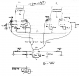
Not going to work. Several reasons.
[1] 6SG7 valve is mis-wired.
[2] No apparent input, except if we infer that the triodes at the bottom, on grid, are input. Draw it right!
[3] No amplification from the lower triodes, assuming that the unshown input is actually there.
[4] Exact same phase from each triode's (non-existent gain) going to both valves, normally made complimentary thru a so-called phase splitter. (which really is a phase inverter)
My recommendation is to start over. Do not draw both channels. Just stick to one — the other will be an exact rubber-stamp, and so is obvious. I'd also draw it “conventionally”, with input on left, feeding your voltage-amplification triode stage, and that feeding your output stage, again to the right. And it, in turn, powering the output transformer, positioned “conventionally”.
The reason I'm strongly advocating use of the left-to-right convention, is because it makes it WAY easier both to discuss in forums like this, and because all the parts clearly stand out “in the right spot”, for others to admire.
OK?
⋅-⋅-⋅ Just saying, ⋅-⋅-⋅
⋅-=≡ GoatGuy ✓ ≡=-⋅
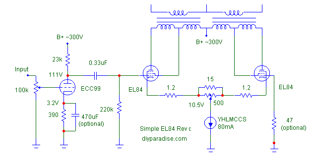
Here is an example of a self-splitting (no phase splitter) amp that works. Not the actual example i was looking for but much the same. You can achieve about half the power (so i understand) from if you put a phase splitter in front of it…
dave
dave
Attachments


Still puzzled about the 6sg7 tubes as output tubes.
6sg7 is a variable mu pentode is for IF and RF amplification
6sg7 is a variable mu pentode is for IF and RF amplification
Have a look at this circuit.
The negative feedback circuit has been cropped a bit and wraps around the tone controls in the full circuit.
It gives you a three tube plus rectifier 25W amplifier.
The circuit will work with EL34/ECC83 that can be bought new on the web too.
The negative feedback circuit has been cropped a bit and wraps around the tone controls in the full circuit.
It gives you a three tube plus rectifier 25W amplifier.
The circuit will work with EL34/ECC83 that can be bought new on the web too.
Attachments
Not quite sure why you are skipping phase inverters.
You can do it two ways with valves either with one triode with same resistor in anode and cathode (cathodyne) or using LTP technique.
Both are on the internet.
See:
The Valve Wizard
You can do it two ways with valves either with one triode with same resistor in anode and cathode (cathodyne) or using LTP technique.
Both are on the internet.
See:
The Valve Wizard
Do you think I need any output transformer negative feedback regardless of using 6SG7 vs 6SN7?
Depends how much warmth you want in the sound.
Guitar amps tend not to use feedback to get some colour in the sound.
Hi fi amps usually have negative feedback.
#1. What purpose do the 3uF caps serve?
#2. The 6SG7 has a 3W plate dissipation rating. I don't see any triode curves, did you find any? Without the phase inverter this is a 1W amp at best, with the phase inverter 2W would be an achievement.
This would be as silly as doing something like putting a resistor in parallel with the coupling cap at the output of a headphone amp.
Here is an example of a self-splitting (no phase splitter) amp that works. Not the actual example i was looking for but much the same. You can achieve about half the power (so i understand) from if you put a phase splitter in front of it…

dave
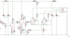
I did an exhaustive look at the self inverting output stage 2-3 yrs ago. Some of the results were shewn in this forum. And you are correct, the available output is about half what is otherwise possible. The cct must be operated Class A only. Saving a single triode in a driver is not a good return for a result that does not deliver.🙂
I tried cathode tails of resisters, NFETS & chokes. Choke tails delivered the best results. Examples of self inverting stages go back to WW2. I would put this cct in the category of 'don't waste your time'.😀
Attachments
#1. What purpose do the 3uF caps serve?
None whatsoever. Is it surprising?

Huh, coupling caps? They can help to protect from overloading the previous stage. The four 6SG7's I have currently are quite "hot". And the planned 12AU7 will stay in.
On another note, a very important question, does anyone think a mic transformer will survive in the 600 CT : 600 CT position?
On another note, a very important question, does anyone think a mic transformer will survive in the 600 CT : 600 CT position?
Last edited:
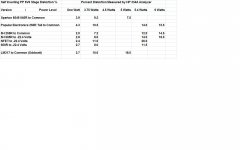
Self Inverting Output Stage Some Test Results
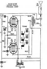
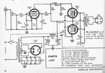
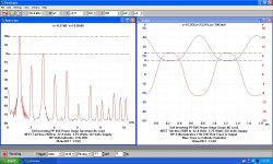
For the curious & others here are some of the D% measurements taken on various versions of the PP 6V6 tail on the test cct. The test cct is essentially the same as the PP 6V6 amp in Popular Electronics Magazine with the exception the driver is a triode connected 6AU6 instead of the pentode connected 6SJ7 on the schematic.
The Self Inverting stage requires 2X the drive of an ordinary PP stage.
One example of many Scope & D% shows lots of distortion even at low power.
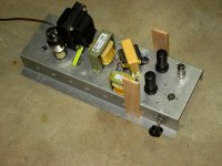
There is a photo of the 'mule' test chassis.🙂
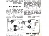
The Sparton 8549 is an ordinary receiver we would find on sale in a 40s electronics store.
For the curious & others here are some of the D% measurements taken on various versions of the PP 6V6 tail on the test cct. The test cct is essentially the same as the PP 6V6 amp in Popular Electronics Magazine with the exception the driver is a triode connected 6AU6 instead of the pentode connected 6SJ7 on the schematic.
The Self Inverting stage requires 2X the drive of an ordinary PP stage.
One example of many Scope & D% shows lots of distortion even at low power.
There is a photo of the 'mule' test chassis.🙂
The Sparton 8549 is an ordinary receiver we would find on sale in a 40s electronics store.
Attachments
I did an exhaustive look at the self inverting output stage 2-3 yrs ago. Some of the results were shewn in this forum.
There is an even earlier thread somewhere on the same circuit.
dave
- Home
- Amplifiers
- Tubes / Valves
- Push pull output transformer, no phase splitter?