Hmmm. If it's a ring structure to create a pseudo spherical wavefront, and the bias sheet has significant resistivity requiring a long charging, can the audio signal capacitively modulate the center membrane sufficiently to change the wavefront geometry? Is the center membrane a film with deposited conductance on both sides, so capable of supporting a differential voltage through it's thickness? That would imply a directivity vs DC voltage level caused by lateral gradients in the bias film charge. Again, that would depend on the film electrical time constant and assumes the recent statement of film bias settling time is accurate.
Polar plots vs DC bias would be the tell.
Jn
For the first time you start wondering how the thing might work, that's a good start.
1) The rings are all driven with a certain delay with respect to each other.
The very flexible membrane with a thickness of only 3u is acting as if it also has individual rings, so yes indeed, the wavefront is changed effectively.
See first image below.
2) The membrane is only covered on one side, covering both sides would not bring anything extra.
As seen from the two Stators that are differentially driven, the 3u foil takes no part in the electrical equation.
3) As mentioned a few times, the time constant of charging the film with a constant Charge is very low.
If the charge would not stay constant, the capacitance would change when moving in such a way that it would lead to severe non linear distortion.
That's why this time constant must be kept below the lowest reproducible frequency.
4) A polar plot is added.
Hans


Life in general very few people I trust. In audio I don't trust anyone to tell me how something will sound. No point. As Scott said some years back describing audio is only really valid in the moment as a shared experience.
Could be a misunderstanding, as I'm not talking about "blind trust" which would IMO mean accepting of everything said.
Trust in this sense just means, that I'ver got the impression that the person acts resonable, has some listening skills and does not claim things out of the blue.
So, if such a person tells me something about a hearing impression, then it is reason for me to take it seriously; assuming that we all know and agree that humans are not infallable.
Taken it seriously means, trying to find out if I'm able to duplicate it and even find a correlation to some technical differences.
Still no. I don't have their ears, music tastes, system or room. I see no common ground on listening impressions. Technical information I will take seriouslyTrust in this sense just means, that I'ver got the impression that the person acts resonable, has some listening skills and does not claim things out of the blue.
duplicating measurements yes. listening correlation is currently not something I do.Taken it seriously means, trying to find out if I'm able to duplicate it and even find a correlation to some technical differences.
2) The membrane is only covered on one side, covering both sides would not bring anything extra.
As seen from the two Stators that are differentially driven, the 3u foil takes no part in the electrical equation.
Correction to the above.
It should be: As seen from the two Stators that are differentially driven, the coating takes no part in the electrical equation.
It's function is to charge the membrane with a constant and uniform charge density.
Sorry for this error.
Hans
Last edited:
Interesting, now we could be getting to the root of the "wife commenting from the kitchen" dilemma. Another data point for me 🙂So, if such a person tells me something about a hearing impression, then it is reason for me to take it seriously; assuming that we all know and agree that humans are not infallable.
Richard, just had an odd thought..
Is the center film coated on both sides or only one?
I ask because I use kapton films for quench spreading heaters on the niobium tin quadrupoles, they are metalized only on one side. We hi pot them to 5kv using a conductive brush wand as a pinhole would be destructive in 4.5 k helium.
During hi pot, the backside of the kapton is capable of supporting huge charge gradients, to the tune of kv per cm, and if the ambient is below 20 RH, it will hold it for days. I stress in my hi pot training class to short the entire surface much longer than the hi pot test time, as kapton is also notorious for dielectric absorption and will recharge 20 to 40 percent of test value after being directly shorted.
John
and if RH =80%
?
-Richard
Syn08, I'll give everyone the benefit of doubt as long as possible, but now it is clear that you're quite often simply lying. You claimed having posted a source for your critic post on Oohashi although you didn't post one back then. You claimed that you've written the critic yourself (and at the same time claimed to have posted a source for it, one can not make up this stuff), you lied about me contorting the truth and now you started the post again with another lie about me "dancing around".
Good to see that you've learned something when reading my posts, namely in this case that before any experiment, a hypothesis must be clearly stated and that the design of the experiment to examine the hypothesis follows in the next step and usually leads to different experiments.
Quite contorted fiction ("observation are apparently valid" but "straight wrong observation"), isn't it?
You've a very vivid imagination and indeed I think most people (at least outside the special cult section) get it.
If you now start to find real examples where I did something of the kind that you've imagined above, that could help your case.
Btw, as you've claimed that "opamp difference audibility" is non-related to " cable difference audibility" and further, that one can't draw conclusions from taste sensory methodology experiments to auditory sensory experiments, you should find some corrobation for these quite "interesting" claims; you know, it's about extraordinary claims and the need for extraordinary evidence ......
Good to see that you've learned something when reading my posts, namely in this case that before any experiment, a hypothesis must be clearly stated and that the design of the experiment to examine the hypothesis follows in the next step and usually leads to different experiments.
<snip>
All these are observation are apparently valid, but they are in the background either irrelevant or straight wrong observation (I was about to write full of four asterisks, but I corrected myself).
Quite contorted fiction ("observation are apparently valid" but "straight wrong observation"), isn't it?
There's more here than could be put in a few sentences, but I guess everybody got the drift.
You've a very vivid imagination and indeed I think most people (at least outside the special cult section) get it.
If you now start to find real examples where I did something of the kind that you've imagined above, that could help your case.
Btw, as you've claimed that "opamp difference audibility" is non-related to " cable difference audibility" and further, that one can't draw conclusions from taste sensory methodology experiments to auditory sensory experiments, you should find some corrobation for these quite "interesting" claims; you know, it's about extraordinary claims and the need for extraordinary evidence ......
Matt,
The comment I get from the kitchen is ‘turn that dang thing down’
My wife enjoys meditation music played at low levels through her galaxy.......most of my stereo time is when the cats away! 🙂
The comment I get from the kitchen is ‘turn that dang thing down’
My wife enjoys meditation music played at low levels through her galaxy.......most of my stereo time is when the cats away! 🙂
Still no. I don't have their ears, music tastes, system or room. I see no common ground on listening impressions. Technical information I will take seriously ....
Interesting; intersubject differences are quite substantial. 🙂
Is the audio field an exception or do you feel the same about other interests, like books, movies or restaurants and recommendations/evaluations?
.....duplicating measurements yes. listening correlation is currently not something I do.
The measurement brings us back to the question about the correlation between measurements (or measured differences) and hearing sensations.
Sounds kinda lonely Bill,
I’d prefer to think my audio hobby is a like minded shared experience.
I’d prefer to think my audio hobby is a like minded shared experience.
For the first time you start wondering how the thing might work, that's a good start.
Good attempt at saving face. Understand it is not a contest.
Yah, I know that. From Richard's schematic, the electrical delay structure was obvious. However, the schematic did not provide the physical profile, so it was not possible to determine if it was a vertical based delay, a horizontal delay, or a circular delay.1) The rings are all driven with a certain delay with respect to each other.
The very flexible membrane with a thickness of only 3u is acting as if it also has individual rings, so yes indeed, the wavefront is changed effectively.
Vertical directionality I could possibly see being desired, horizontal would have been something I would have thought more desirable to create wider dispersion as a linear source, circular to create a point source produces a cleaner listener based directionality.
In addition, the transition from a planar source through linear into point alters the IID localization characteristics within the listening field. (scottjoplin, bet you didn't see that coming...)😉
2) The membrane is only covered on one side, covering both sides would not bring anything extra.
As seen from the two Stators that are differentially driven, the 3u foil takes no part in the electrical equation.
That is a fundamental flaw in understanding.
That means that the film can be charged through it's thickness in direct proportion to the inducing audio voltage, that induced voltage caused by the capacitive divider of the film, gap to stator, and relative permittivity of air (1) to the film permittivity (3). The lower the DC voltage of the rotor (assuming you are consistent in terms) the higher the ratio of induced charge to DC bias voltage. IOW, the lower the DC bias, the more the audio signal will affect the acceleration of the rotor. Note that this is EXACTLY the physical response mechanism I pointed out that I have wrestled with to fix machines at work.
Having the film metalized on only one side is a clear fundamental flaw in electrostatic motor design. I am somewhat taken aback that this trivially understood mechanism has been ignored (although I have to admit, I am not surprised.). It is also a very good candidate for the observations Richard has made regarding the line voltage susceptibility.
Note: this capacitive divider effect was trivially noticeable on the old tube style tv's, the hv lead to the crt would get incredibly covered in dust by electrostatic attraction despite the fact that the insulation is rated for the voltage. A little understood phenomena is that a simple insulated wire in air will have the internal voltage present on the outer surface of the insulation because the capacitor formed by the insulation is thin with a permittivity of 3, while the external air has a value of 1 and the external plates are far away. That is one reason the NEC specifies wires in tray be categorized by insulation rating. As you bring a finger closer to the wire, the capacitive change will supress the voltage at the wire surface you are approaching, so you never feel the voltage as a spark.
4) A polar plot is added.
Thanks for the information.
When I said polar plot, I assumed it was understood that I meant polar plot vs frequency vs DC bias voltage.
That has been the discussion.
jn
Last edited:
You know this clarification / call out isn't going to stop Markw4 from pursuing his mission here.But, there is NO excuse for sloppy methodology. It is all in the 'demonstrably affected'. In none of your posts have you ever given acceptable proof, nothing has been demonstrated.
The reason you don't give proof is NOT because it is hard, expensive or time consuming. It is because you are chasing dragons. Hard facts will burst your bubbles.
We bag the entity being hipotted by covering it with a plastic film, taping it to the granite block, run a bottle of nitrogen gas though the bag to dry it out, then test later. masking tape is your friend 😀... Open films recover in an hour or two, fully cryostatted magnets can require up to a day for the moisture to be pulled out of the collared structure. 80%, pfftt. Several weeks a year it's in the high nineties, and they are constantly opening the rollup door to drive trucks in for loading and unloading.and if RH =80%
?
-Richard
jn
This is the room where the editor John Atkinson does his listening evaluations.I don't now how Stereophile's room looks, but it looks like a non optimal one for ESL's.
Attachments
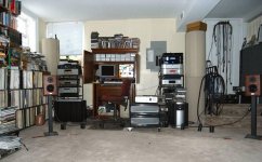
Oooh, speaker cable standoffs made from myrtle wood.
The upstream signal distribution behind the left rack....
wait, I have seen something similar in 2011:
< Album Archive >
Zoom in for maximum joy.
The upstream signal distribution behind the left rack....
wait, I have seen something similar in 2011:
< Album Archive >
Zoom in for maximum joy.
Last edited:
Now that’s something I can relate to Gerhard!
But the wooden blocks might actually serve a purpose on carpet against static?
Not quite sure what the draw to myrtle is?
But the wooden blocks might actually serve a purpose on carpet against static?
Not quite sure what the draw to myrtle is?
<snip>
This is exactly "dancing around the issue", AKA bull four stars. Smearing, straw man, character assassination, etc... anything goes but addressing the core problem (which was not requested, BTW). Shows how low one can go to promote and defend his agenda.
Carry on, ultimately I don't give a rat's three stars. The bees in your bonnet are doing a great job.
Last edited:
Show me a speaker with a better dispersion.Vertical directionality I could possibly see being desired, horizontal would have been something I would have thought more desirable to create wider dispersion as a linear source, circular to create a point source produces a cleaner listener based directionality.
You are probably not aware that with fixed delay times, it is not possible to create a point source for all frequencies.
You must have heard something without having a clue what it means. 😀In addition, the transition from a planar source through linear into point alters the IID localization characteristics within the listening field. (scottjoplin, bet you didn't see that coming...)😉
Again, the film is just charged by the HV with a surface square resistance of 10^6 Mohm and not charged by the audio signal.That means that the film can be charged through it's thickness in direct proportion to the inducing audio voltage, that induced voltage caused by the capacitive divider of the film, gap to stator, and relative permittivity of air (1) to the film permittivity (3). The lower the DC voltage of the rotor (assuming you are consistent in terms) the higher the ratio of induced charge to DC bias voltage. IOW, the lower the DC bias, the more the audio signal will affect the acceleration of the rotor. Note that this is EXACTLY the physical response mechanism I pointed out that I have wrestled with to fix machines at work.
Please stop playing to be Einstein
Yes you are right, Peter Walker was a dumbo who had no idea what he was doing, despite all backing up from the local university.Having the film metalized on only one side is a clear fundamental flaw in electrostatic motor design. I am somewhat taken aback that this trivially understood mechanism has been ignored (although I have to admit, I am not surprised.).
Even better would have been to replace the membrane by alu foil, that would have saved the dilemma which side to coat, doesn't it ?
When I said polar plot, I assumed it was understood that I meant polar plot vs frequency vs DC bias voltage.
The polar plot was meant to show the effectiveness of the sound dispersion with the delayed rings that you doubted to work.
If you want polar plots with different HV voltages, just do it yourself an stop instructing others what to do.
Hans
Last edited:
...qualifying them as sensory illusions (in our case) may not be "nice"...
It would not be scientific either. Illusions are something that results from a cause outside the individual. So, if there are perceptual illusions as you say then what are the causes in the audio system the produces illusions in humans?
We all know about the stereo illusion.
How about non-stationary distortion for another source of your so-called illusions? You haven't looked to find causes so you have some work to do before pronouncing that there are more illusions.
Syn,
Let’s just say for a moment all the people that hear differences in caps, speaker cable, amps (Even when level matched), dacs etc..... were actually straight up delusional.
In your version of this audio utopia where everything correctly engineered and not broken sounded exactly the same, what would be left to discuss..... aesthetics?
- Status
- Not open for further replies.
- Home
- Member Areas
- The Lounge
- John Curl's Blowtorch preamplifier part IV