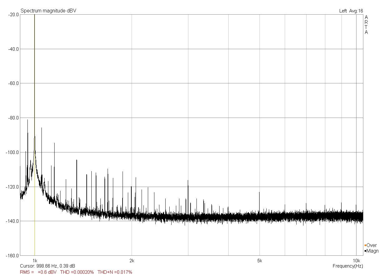
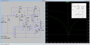
Here's a first result. I tried to get closer to 1kHz center frequency, arrived at almost 999Hz with a first try. The matching between the passives must be horrible though, because I can get only barely down by 40dB now 🙁. I'll add some more trimpots and adjust the heck out of them, just to see how deep I can actually get at all. Maybe the notch is just too narrow already and gets swamped by the comparatively huge bin size of the FFT? I'll have to find out.
Nonetheless, it basically works as expected in many aspects. The level at 2kHz for example is down by 0.2dB, pretty much what the sim said. The relay trimmer does work, too, with a nice clicky action. The adjustable range is roughly 1.7Hz, which is probably a bit too fine to be useful. I'll probably ditch the smallest value of 1R, exchange it for 32R (which would be the next step up from the now highest value of 16R) and rewire the uC outputs to the relay drivers, which I have conveniently laid out in color coded wire links 😎.
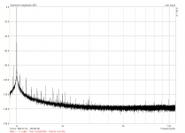
Here's a soundcard loopback-through-the-notch run with the output set to -6dBV. I have used the frequency response correction in ARTA, so the calculated THD values should be correct. Pretty noisy affair, but that was to be expected with everything lying bare on the bench, with lots of wires sticking out like antennas everywhere....

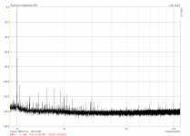
This is the same run, but with the passive Twin-T part bypassed and without any frequency compensation. The noise looks much better now (far from clean though, I know), but the THD got a little worse actually due to an increase in the 3rd harmonic.

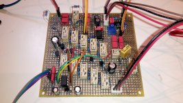
This is what the whole mess looks like right now. The flying resistors are the trim resistors, which I supposedly tweak to the correct value and then solder in for good. The unpopulated DIL socket up to the right is for an additional gain stage afterwards, but not used right now. Bottom left is an ATTiny13 running off the internal 128kHz watchdog timer (no need for 8MHz here) and constantly polling a rotary encoder to switch the 5 sets of relays. There are three more relays, which will hopefully take up their duty to switch a set of capacitors (10nF and 1nF) and the power supply to two of Victor's oscillators, so I only need one switch for 1kHz and 10kHz operation. Not shown on the photo but to the right of the board is a big and chunky variable capacitor from a 1970's vintage tube radio, in parallel with one set of capacitors, to adjust the notch depth to a maximum. Works like a charm and has a nice tactile feeling to it.
Nonetheless, it basically works as expected in many aspects. The level at 2kHz for example is down by 0.2dB, pretty much what the sim said. The relay trimmer does work, too, with a nice clicky action. The adjustable range is roughly 1.7Hz, which is probably a bit too fine to be useful. I'll probably ditch the smallest value of 1R, exchange it for 32R (which would be the next step up from the now highest value of 16R) and rewire the uC outputs to the relay drivers, which I have conveniently laid out in color coded wire links 😎.
Here's a soundcard loopback-through-the-notch run with the output set to -6dBV. I have used the frequency response correction in ARTA, so the calculated THD values should be correct. Pretty noisy affair, but that was to be expected with everything lying bare on the bench, with lots of wires sticking out like antennas everywhere....
This is the same run, but with the passive Twin-T part bypassed and without any frequency compensation. The noise looks much better now (far from clean though, I know), but the THD got a little worse actually due to an increase in the 3rd harmonic.
This is what the whole mess looks like right now. The flying resistors are the trim resistors, which I supposedly tweak to the correct value and then solder in for good. The unpopulated DIL socket up to the right is for an additional gain stage afterwards, but not used right now. Bottom left is an ATTiny13 running off the internal 128kHz watchdog timer (no need for 8MHz here) and constantly polling a rotary encoder to switch the 5 sets of relays. There are three more relays, which will hopefully take up their duty to switch a set of capacitors (10nF and 1nF) and the power supply to two of Victor's oscillators, so I only need one switch for 1kHz and 10kHz operation. Not shown on the photo but to the right of the board is a big and chunky variable capacitor from a 1970's vintage tube radio, in parallel with one set of capacitors, to adjust the notch depth to a maximum. Works like a charm and has a nice tactile feeling to it.
Attachments

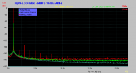
As promised my measurement using Low THD Osz. from Victor (LME OPAMP) with balanced connection. The ADC is the RME ADI-2 Pro with M/S connection, this means dual input in parallel and ~3dB noise gain.
1) Normal spectrum dBc : ADC -2 dBFS on 19dBu range = ~ 17 dBu
2) Active Notch Trace dBc : ADC on 4dBu with compensated 15dB gain (19 - 4dBu)
3) Active Notch idle noise contribution
In other words, the active T-Notch alters / adds to much Noise (will also component dependent).
A passive notch would lower the LDO Noise Bell & Harmonic's into the noise floor and measurement of the LDO side noise & Har's would be impossible to compensate (IMHO).
How much the Notch adds THD, do the chosen components, is hard to measure too. IMHO requires high end measurement gear.
Hp
Attachments
Interesting - I've been playing with Fliege notch filters for targeting 50Hz mains induced ripple. I read the point about LDO being oscillator but it's all interesting.
Let me share the Shibasoku notch here. They instrument uses 3 in series. Each has about 40 dB insertion loss with around a 1% band reject at 50 dB. The instrument uses a lot of relays to tune them and is not practical to copy. However the concept of cascaded notches could make sense.
I made the sim to figure out how to tune and tweak the circuit since Shibasoku has been really bad about sharing service info. One key is that the opamp driving the feedback into the notch is critical. It needs to be really really low distortion. The opamps in the sim are just placeholders.
One possibility would be a notch with 40 dB of gain into a conventional analyzer which could push the distortion floor 40 dB lower.
Attachments
Let me share the Shibasoku notch here. They instrument uses 3 in series. Each has about 40 dB insertion loss with around a 1% band reject at 50 dB. The instrument uses a lot of relays to tune them and is not practical to copy. However the concept of cascaded notches could make sense.
I made the sim to figure out how to tune and tweak the circuit since Shibasoku has been really bad about sharing service info. One key is that the opamp driving the feedback into the notch is critical. It needs to be really really low distortion. The opamps in the sim are just placeholders.
One possibility would be a notch with 40 dB of gain into a conventional analyzer which could push the distortion floor 40 dB lower.
Hi Demian,
This looks like quite a complex notch. Are there 3 of these in series?
Also, it is hard for me to identify what kind of notch this is. It does not look like a twin T. Is it a variant of a bridged T? I must admit I just took a quick glance at it.
How do they auto-tune these 3 notch filters in the analyzer. Looks like it would be very difficult.
Cheers,
Bob
Hi Bob, everyone,
I believe the notch in Damian's post is nearly identical to the notch in the HP339A, aside from omission of the autotune LDRs.
For those unfamiliar, U1 corresponds to A3U3, U2 to A3U4, and U4 to capacitance neutralizer A3U2. Sections 8-31 through 8-34 of the service manual describe circuit details. U3 is exploratory in the simulation, perhaps?
https://literature.cdn.keysight.com/litweb/pdf/00339-90001OPT001.pdf?id=857565
Best,
Steve
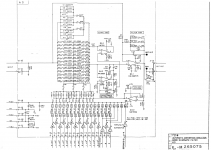
Bob: Yes there are three in series tuned with relays by the frequency counter. No analog multiplier/jfet/LDR or analog switches to degrade the distortion. But something like 16 or so relays in each section. I think it is a bridged T with a lot of details which is why the sim is so complex.
U3 drives an active shield I think. I'm no longer sure. I did that some years ago. . .
I attached the actual circuit which may be a little easier to follow.
FWIW the modified AD725D will get -119 dB THD+N midband. But what a herculean effort.
U3 drives an active shield I think. I'm no longer sure. I did that some years ago. . .
I attached the actual circuit which may be a little easier to follow.
FWIW the modified AD725D will get -119 dB THD+N midband. But what a herculean effort.
Attachments
Bob: Yes there are three in series tuned with relays by the frequency counter. No analog multiplier/jfet/LDR or analog switches to degrade the distortion. But something like 16 or so relays in each section. I think it is a bridged T with a lot of details which is why the sim is so complex.
U3 drives an active shield I think. I'm no longer sure. I did that some years ago. . .
I attached the actual circuit which may be a little easier to follow.
FWIW the modified AD725D will get -119 dB THD+N midband. But what a herculean effort.
Thanks for the info.
A hurculean effort indeed. Do you know what year this came out?
So there is no auto-tune circuitry? Or I guess the fine granularity of the relay setup is adequate for the relays to be switched to be right on frequency?
Do they use the same/adequate granularity on the source oscillator to have the analyzer track the internal oscillator? Or is the oscillator just accurate and close in frequency and the relays are twiddled to center the notch on the oscillator frequency?
Are all 3 notches tuned to the exact same frequency, or are they slightly different so as to widen the notch a bit?
I'm surprised that they were not able to use a state variable notch filter with amplitude and frequency auto-tune. It is true that JFET tuning elements can introduce distortion, but the fact that Victor uses a JFET in his oscillator agc and achieves such remarkable results suggests that a well-done JFET-based auto-tune could do the job, especially if pains are taken to minimize the tuning range needed.
State variable bandpass filters are fairly easy to tune for amplitude and center frequency. The notch is formed by subtracting the bandpass output from the input. This results in a very sharp notch.
Cheers,
Bob
The first generation dates from the 1980's. It also has the harmonic analyzer function implemented with a 1970's era ADC. I also recently got an AM70A which has both generator and analyzer in one box. Its the most recent variation but its largely the same. The discrete input amp has been converted to SMT on a module and some of the opamps have been upgraded a little. Still mostly the same.
The input signal goes to a frequency counter that determines which relays to engage. The frequency steps seem to be like .5% so it has full coverage.
The documentation is pretty sparse so I don't have any alignment info but it seems the three "BEF" (band elimination filters) are all on top of each other.
I think even Victor has acknowledged that the reason the fet works well in his oscillator is the fixed tuning and narrow level range. For the oscillator in the AM70A they use a motorola analog multiplier so the designers are OK with that approach but seem to focus on passive tuning for everything.
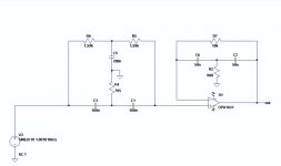
Attached a T-Win Bridge Notch, a copy from a diy'er.
more to come...
While all feedback notches will show a rising noise bell (IMHO is like oscillating).
How large this noise peak will be shown is R / C value dependent and also Q dependent as given from the R-f1 / R-f2 feedback attenuation.
IMHO the active T-Notch is a night mare. Also you will see some strange signals thinking that are harmonic's, but are/where a multiple of the notch oscillations... 😀
Hp
Attachments
FWIW the modified AD725D will get -119 dB THD+N midband. But what a herculean effort.
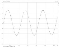
Question: how the notch frequency responce looks like?
While with low feedback gain, the Q looks very low and may the H2 attenuation would be a view dB's only... ??? and while stacked things gets not better!
Also the idle noise figures who limits the overall thd+n figures..
Hp
Last edited:
I'm assuming the twin-T and the bridged-T are both tuned to the desired notch. Unless my thinking is upside-down, the 2nd stage in Hp's #30 post would have unity gain at frequencies well removed from the bridged-T center and roughly 20dB gain at center frequency. I believe that would be opposite to what's desired.
For another test I have removed the bootstrap and managed to get a -100dB notch. Due to the now passive Twin-T response (with a buffer afterwards) the 2nd is down by 9.XdB and so on. ARTA can compensate that with a preceding frequency response measurement though.

The "measured" distortion is down to 0.000076%, that's four zeros!
This is with the Twin-T bypassed. 0.00016%, only three zeros.
I noticed a difference of about 4dB in RMS level, that's probably due to the frequency correction being not spot-on, or the notch frequency drifting a bit. Not sure how much impact that has on the THD calculations though.
Attachments
You really don't need to accurately know the depth of the notch. What you need to know is the attenuation of the harmonics.
Example: you know (from measurements) that your notch attenuates the 2nd by say 4dB.
You feed the notch with 1V, and set the dBr ref of your test equipment/software* to -4dBV, and presto! You measure accurately the 2nd level against the fundamental, irrespective of the notch depth.
Jan
*most measurement software packages allow this, otherwise do it mentally ;-)
I'm assuming the twin-T and the bridged-T are both tuned to the desired notch. Unless my thinking is upside-down, the 2nd stage in Hp's #30 post would have unity gain at frequencies well removed from the bridged-T center and roughly 20dB gain at center frequency. I believe that would be opposite to what's desired.
The used active notch as I used in the measurements are unity gain.
The given #30 post bridged-T I did not checked/measured/simulated unity gain & noise figures! It is just an alternate topologie given from a DIY'er to validate.
Hp
For another test I have removed the bootstrap and managed to get a -100dB notch. Due to the now passive Twin-T response (with a buffer afterwards) the 2nd is down by 9.XdB and so on. ARTA can compensate that with a preceding frequency response measurement though.
I noticed a difference of about 4dB in RMS level, that's probably due to the frequency correction being not spot-on, or the notch frequency drifting a bit. Not sure how much impact that has on the THD calculations though.
You really don't need to accurately know the depth of the notch. What you need to know is the attenuation of the harmonics.
Example: you know (from measurements) that your notch attenuates the 2nd by say 4dB.
You feed the notch with 1V, and set the dBr ref of your test equipment/software* to -4dBV, and presto! You measure accurately the 2nd level against the fundamental, irrespective of the notch depth.
Jan
*most measurement software packages allow this, otherwise do it mentally ;-)
Again, IMHO the passive notch with the inverse bell freq. response has the drawbacks:
- Shifting the noise bell of the low THD-LDO into noise floor
- Sifting the 2h.. may up to 5H into the noise floor too
Using a correction curve will rescale to unknow content (signal & noise), may to hell. That's why I am looking for better solution 😀
What do not exists as my Professor would say (as in German): Wer misst, misst Mist 😀
You really don't need to accurately know the depth of the notch. What you need to know is the attenuation of the harmonics.
Example: you know (from measurements) that your notch attenuates the 2nd by say 4dB.
You feed the notch with 1V, and set the dBr ref of your test equipment/software* to -4dBV, and presto! You measure accurately the 2nd level against the fundamental, irrespective of the notch depth.
Jan
*most measurement software packages allow this, otherwise do it mentally ;-)
Absolutely true if you are using a straight FFT. But the lack of fundamental can be problematic if using a conventional THD analyzer. Also, some known amount of fundamental can be convenient with FFT as showing a reference marker. It provides a good sanity check and can help sometimes. Also, if you are using something like a QA401, which takes all the FFT products and produces a THD number, the presence of a known amount of fundamental can allow reasonably accurate calculation of THD, where you just need to incorporate the known fundamental attenuation into the interpretation of the result.
In most cases where we use a twin T to enhance measurement sensitivity of a distortion measurement, either by conventional THD analyzer or by FFT, we really only need 40 dB or so of twin T attenuation to get more than adequate enhancement, so there could be something to be said for having that 40 dB of notch attenuation being reasonably well known.
Maybe a twin T filter box with a switch for max obtainable notch depth or known 40 dB notch depth would be a good option. This is similar to the approach I took in the distortion magnifier, where I have a switch to select maximum cancellation, 40 dB cancellation (i.e., 40 dB of magnification), or 20 dB of attenuation.
Cheers,
Bob
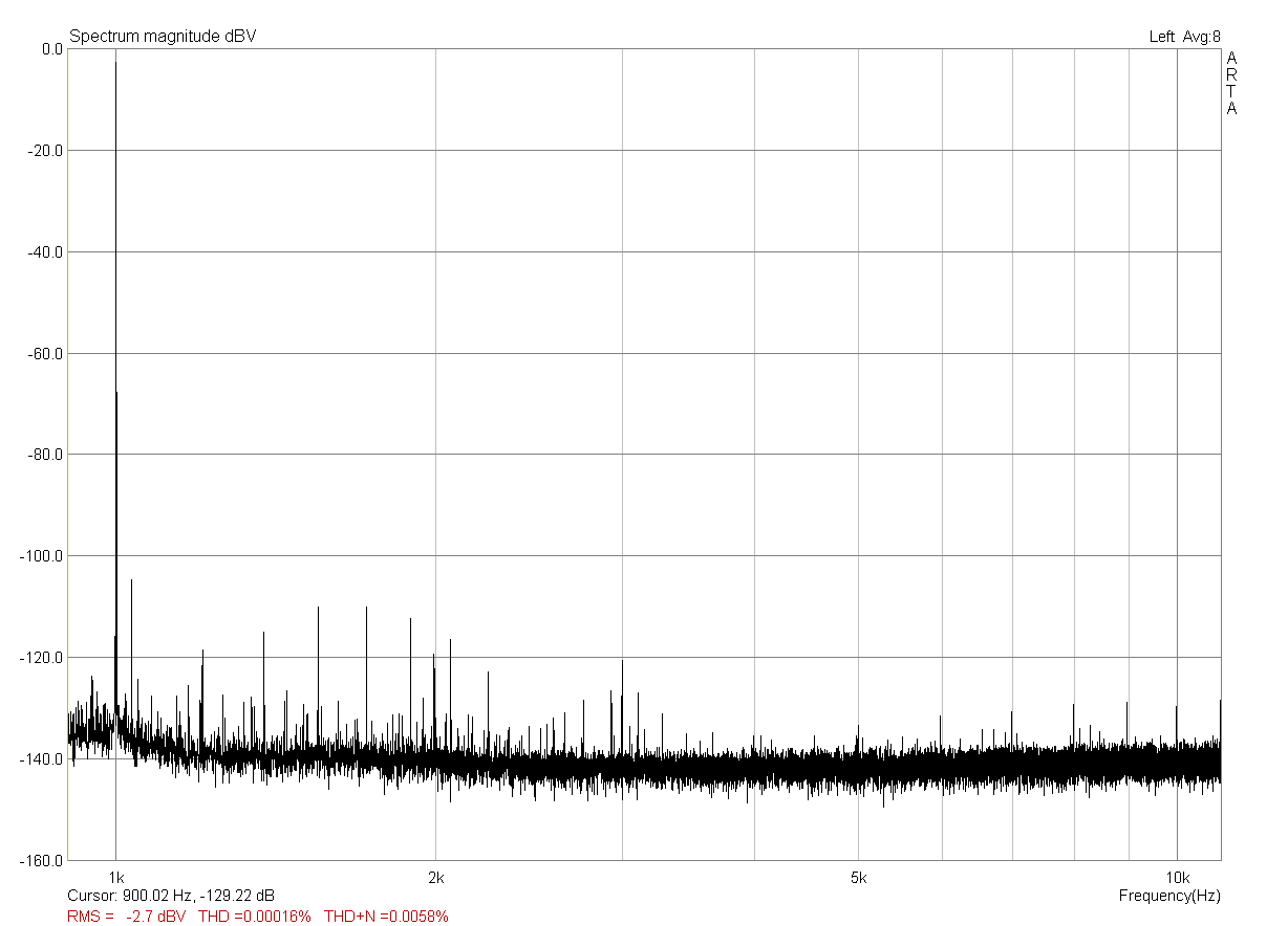
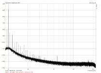
I have just tried (again...) to adjust the Active Twin-T to the deepest possible notch depth, fed it with Victor's oscillator this time and put a single 20dB opamp gain stage behind it. See the attached results.
Victor's oscillator measured 2.156Vrms or 6.67dBV. ARTA then measured -42,46dBV for the fundamental, which is actually 20dB lower at -62,46dBV, so the notch depth calculates to somewhere close to 70dB.
If I do the same calculation for the 2nd harmonic, starting out at -120,5dBV (without any compensation, since the bootstrap took care of that), I arrive at -147dB or 0,0000045% distortion. Does that sound reasonable? The oscillator could be that good, and there are no more harmonics to be seen in the spectrum...
Attachments
Here again once more... I love here the noise figures seen at https://www.edn.com/three-op-amp-state-variable-filter-perfects-the-notch/
Built a prototype of this circuit. Due to being out of stock of capable opamps, I have used a TL084 that was left in the parts bin.
Some observations:
The circuit actually works fine, achieving a notch depth of around 60dB easily without matching of any passives and using a single potentiometer to adjust the notch frequency.
The noise spectrum that I could observe seems to be even lower than what I can achieve with my Active Twin-T prototype, even though the TL084 used here is more noisy than the OPA2134 used there.
I had to put a 100nF between the opamp's V+ and V- to stop some 1MHz oscillations at the filter output.
The circuit as-is is only good for around 1Vp input. The first opamp stage has 20dB gain and will easily run out of output swing when overdriven.
Even when driven with only 0.6Vp from Victor's oscillator, there are lots of harmonics to be seen already, with the 2nd and 3rd around -108dB. This is probably due to the bad performance of the humble TL084, necessitating some high-performance, low-distortion opamps to make this circuit useful. Maybe some discrete opamps with higher rails might be worth a try here.
Nice to see that you built this up and tried it. Thanks for your observations. I'd love to see how this works when you get really good op amps into the circuit. Have you simulated it and the active twin T to understand the noise performance differences between the two circuits?
Cheers,
Bob
- Home
- Design & Build
- Equipment & Tools
- Measuring LDO with passive/active notches/filter