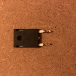
the FEP30DP-E3/45GI-ND is a DUAL diode with one common leg. no need to cut anything, just insert them into a PCB, and solder.
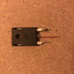
depending how close you cut, you might be able to solder an extension leg, and still use the didoes...
There is your problem, 3 legged diodes should use all the legs, the ones in the guide are 2 legged ones.

Let’s say I was to enthusiastic with this build. I am very grateful to get such a quick and good help from you guys!
I will order new ones, and try again. 🙂
Regards,
Koos
This is a mistake we all make, luckily it teaches us to notice and question what we assume to know 🙂
depending how close you cut, you might be able to solder an extension leg, and still use the didoes...
Thanks for the advise, I will have a look if I have some material to use as a leg.
depending how close you cut, you might be able to solder an extension leg, and still use the didoes...
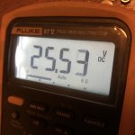
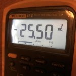
Great! It worked 🙂
Please see the photos attached, I just used solid core copper wire to solder a leg.
PSU is up and running thanks to you guys!
Attachments

Sure. Just make sure they physically fit. (I thiink the pcb supports max 35mm diameter caps?)
If I were to use these capacitors, am I right in thinking the "inrush" is going to be massive? Should I get a soft start board?
I'm not a total noobie, I've built an 834p clone. But I'm no Tesla.
I'm not a total noobie, I've built an 834p clone. But I'm no Tesla.
Or just step up to a 20ohm inrush current limiter (in place of the 10ohm CL-60).
SL22 20005 Ametherm | Mouser Ireland
SL22 20005 Ametherm | Mouser Ireland


I finished the main amp boards and most of the PSU. I'm going to work on the layout in the deluxe 4U chassis. My plan is to mount the PSU on the chassis floor then I'll get some temp wiring done for a test with a dim lite and I have 3 MM also for testing. I've read all the M2x posts from the start, but I'm going to review the initial start up procedures and tests to be sure I get it before I start.
I have a couple of questions please.
The trimmer prongs were offset I bent the middle prong to line up with the 3 inline holes on the PCB. Is that OK?
I bought high intensity LEDs which I put in with the 6.2K resister. It's all I got, it will be bright which I'm going to convince myself and others that it's very cool😎
You see my macho resisters? I now understand the sizing system code of them. I'll be wiser on the next project.🙄
Well I thought I would easily find what the lettering means on the Dale resistors. Not! Apparently I need to order the correct size. I'm having a hard time finding out how to read a Dale. The ones I have are 14.27mm long. I assumed the lettering on it 1740J RN65C would be a code to the size. I don't think so. What does it all mean? The part I get is 2210F. I'll keep looking. Maybe because it's military spec.
- Home
- Amplifiers
- Power Supplies
- diyAudio Power Supply Circuit Board v3 illustrated build guide