I've been interested in the APT-1 power amp since the first time that I read about it.
I followed the "APT 1 power amp – undeservedly forgotten" thread and found an LTSPICE
simulation file posted by unclejed613:
APT 1 power amp – undeservedly forgotten
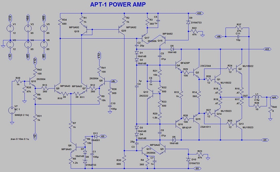
I cleaned up the schematic first just to make it easier to read, then got determined to make
it run. unclejed included a models file for the design but it did not include all the models.
The 1N4733 zener was not there, I made one and put it right into the schematic. The drivers
were not there so I substituted the ones shown in the schematic and found models from
keantoken on here. I made a models file including all of Kean's work called KEANTOKEN.txt
because his file included models from at least 4 people making it difficult to figure out.
I renamed unclejed's model file to UNCLEJED.txt. The 1n4001 model was missing so I
included Bob C's models and used the 1N4004C model.
Some of the models such as the 2n3904 come out of the default LTSPICE library.
I don't know where unclejed got his models and therefore I don't trust them.
I've attached a .zip file with everything and the sim runs but as I said I don't trust the
models. The main reason for doing this was to have an easy to read schematic, perhaps
I'll work more on the sim in the future. The sim runs but who knows about the accuracy.
I followed the "APT 1 power amp – undeservedly forgotten" thread and found an LTSPICE
simulation file posted by unclejed613:
APT 1 power amp – undeservedly forgotten
I cleaned up the schematic first just to make it easier to read, then got determined to make
it run. unclejed included a models file for the design but it did not include all the models.
The 1N4733 zener was not there, I made one and put it right into the schematic. The drivers
were not there so I substituted the ones shown in the schematic and found models from
keantoken on here. I made a models file including all of Kean's work called KEANTOKEN.txt
because his file included models from at least 4 people making it difficult to figure out.
I renamed unclejed's model file to UNCLEJED.txt. The 1n4001 model was missing so I
included Bob C's models and used the 1N4004C model.
Some of the models such as the 2n3904 come out of the default LTSPICE library.
I don't know where unclejed got his models and therefore I don't trust them.
I've attached a .zip file with everything and the sim runs but as I said I don't trust the
models. The main reason for doing this was to have an easy to read schematic, perhaps
I'll work more on the sim in the future. The sim runs but who knows about the accuracy.
Attachments

Last edited:
Q1/Q4 should probably be KSC1845 instead of 2N3904. R41/R42 do not exist, maybe there for sim only? R12/R13 are 39 ohms on my boards even though the schematic in the manual shows 360. Q12 is a KSC1845 also, although the real part is no longer available. I think 1345 if memory serves. Is C10 a patch to avoid the op amp? There is no C10.
The picture is what unclejed posted just with things moved around. He mentioned that
he did not include the DC servo, or other extra circuitry. I think that he did add C10 just
to make the sim work better without the servo.
You probably know that he worked at APT and he mentions in that thread changes in later
revisions and there is mention of resistors going to 39 ohms.
My edits to his sim have a few minor changes to make it run, the driver transistors,
1N4001 changed to 1N4004C, and perhaps a few others.
I simply tried to keep it as close to original as possible and there are many options for
newer transistors.
Thanks for posting, I welcome corrections so that we have a first sim that is accurate to
the original design.
Post where he mentions the change to 39 ohm resistors:
https://www.diyaudio.com/forums/sol...mp-undeservedly-forgotten-28.html#post2520320
https://www.diyaudio.com/forums/sol...mp-undeservedly-forgotten-28.html#post2520320
It would be nice to capture all of unclejed's posts about the APT-1 design and
construction/debug into one text file.
construction/debug into one text file.
So I converted from ltspice format to a system I use for design. During conversion, noticed a couple more nits. The naming is not consistent with the original schematic, so I renamed everything to the original. I also added node names like q1e for the node at the emitter of q1. So the stuff I noticed was R14 should be 360 ohms not 560. Labelled R38 on the original. C1 is 47uF not 100. Labelled C26 on original. Q19 is a 2N3906 not a MPSA92. Labelled Q5 on original. For my purposes I also bumped the nfb cap from 100 to 1000 to be more realistic in modelling the DC servo. I also noted the drive of the input generator a touch high. For 100W out into 8 ohms, should be around 1.3V input (zero-peak)
After all that I ran a sim in ngspice (10ns step) with a 10K sine at the input at 1.3V. Output fundamental was 40V at 10KHz, .033V(-60db) at 20K and .008V(-74db) at 30K. I'm probably going to run a few more sims. The only thing I noticed was some waveform imperfections running at 10KHz+ with 1.8V in. Something is not liking the higher input.
Agreed a summary of the original thread would be nice, but I read thru the 37 pages once. Not sure I want to do that again!
So I noticed some ringing in the sim in the negative cycle around 6MHz. I added a 1nf cap across the 47K resistor to ground for the cascode base bias, both on the positive and negative. Although only the negative seemed to have a large effect. I've attached the before and after plots. I may just add that cap to the boards. It could be an artifact of the sims though. This was with a 10KHz input at 1.33V. Curious if ltspice is also showing this effect.
Attachments
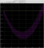

OOps, my bad. It is not the caps that fixed the ring. It is the 360 ohm resistor that the original schematic used instead of the actual 39 ohm resistor that my boards and later schematics have. I am definitely changing that to a 360 like the original schematic. I wonder why it was later changed to a 39.
I'd appreciate a snapshot of your schematic and then maybe one day I'll renumber all the
devices to match yours. I thought that Q19 and Q20 would be the same type since they
form a mirror but of course it is not necessary, and Q20 needs to be a high voltage type.
Do you have models for all the devices?
devices to match yours. I thought that Q19 and Q20 would be the same type since they
form a mirror but of course it is not necessary, and Q20 needs to be a high voltage type.
Do you have models for all the devices?
I changed R14 from 560 to 360, C1 from 100uF to 47uF and the feedback cap from 100u
to 1000 to agree with your sim - thanks for the corrections.
The LTspice sim runs fine at 1.3V or 1.8V in at 20 KHz.
to 1000 to agree with your sim - thanks for the corrections.
The LTspice sim runs fine at 1.3V or 1.8V in at 20 KHz.
I've attached what I am running at the moment. The caps on the cascode zener's do not stop the oscillations with the 39 ohms(my R6/R13) on the front end. When I change only one of the 39's to a 360 on the front end, the caps do stop the oscillations that would occur. I may put the caps in as they do seem to help stabilize. And of course I'll be changing out the 39's to 360's. If you get a chance, try changing the front end R's to 39 (leaving out the caps I added) to see if ltspice oscillates. I was running a time step of 10ns for 1 ms. Thanks
Attachments
Forgot to mention, yes all models were in the zip file you posted. I did have to remove some of the suffixes on the parts to match the device name on the schematic. I also had to create a 5.1V zener from the 6.2v one by changing the bv/vpk values. Not sure how valid that was.
Back to the sim, so I dropped the emitter R's of the front end down even lower (10 and 20 ohms) and still got some ringing. Even 50 ohms seemed to have stopped the ringing. Still baffled why the change was made on the later rev's like mine.
Back to the sim, so I dropped the emitter R's of the front end down even lower (10 and 20 ohms) and still got some ringing. Even 50 ohms seemed to have stopped the ringing. Still baffled why the change was made on the later rev's like mine.
If we are using the same models then they should run the same in the simulator.
Your real hardware doesn't oscillate so why would you trust the simulation?
The suffixes indicate who made the model.
_kq is keantoken with quasisaturation
_c is Cordell
If you remove the suffixes in the schematic without also doing it in the model libraries
then you might pull a model from somewhere else.
I made the models agree with the schematic. Thanks for the info on the suffix info. ngspice has no native models,. I stripped the suffixes from the schematic since I did not know what they meant. I also did back off the 1875 beta to 500 in the model. The devices I bought had around 500. As to the oscillations are for real, I have no way of knowing. No scope, and you can't hear 50MHz. The oscillation is not so great that it would heat anything abnormally either. Simulators are different though. I think you are using ltspice and I am using ngspice.
_c is Cordell
Correction: _c should have been C, which is confusing in cases where C is an hfe grade.
- Home
- Amplifiers
- Solid State
- APT-1 Schematic and Simulation from unclejed613