So I'm looking for the cool tricolor led fade circuit that was on my SA 5.1 preamp. I have seen the circuit on the schematic but cant find it anymore. This used the combo green/red LED and faded from red thru orange to green for the warmup period. Or a circuit that would perform just like it.
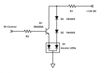
Something like this? Use an input RC filter for a gradual transition, by adding a 100uF/16V capacitor
from the 2N2222A base to ground. Make R2 around 5k, and R1 around 1k.
from the 2N2222A base to ground. Make R2 around 5k, and R1 around 1k.
Attachments
Last edited:
Thank you. I'll play with it on the bench. So when the transistor driven led is fully on the other will be off? Will this give a solid red thru transition to full green.
By the look of it, no. The red will be on all the time, and the green will fade in to make an ugly orange/brown colour 🙂
By the look of it, no. The red will be on all the time, and the green will fade
in to make an ugly orange/brown colour 🙂
This circuit was in a commercial product for years, and worked flawlessly.
I used a red/amber LED, which goes well with visible tubes.
When the transistor is off (0V in), the left LED has no path current and is off.
The right LED is then driven by current from the supply through the two diodes.
When the transistor is on (5V in), the transistor is saturated and its CE voltage is small.
The voltage at the top of the string is now about 2V since the left LED is on, but the string
needs over 3V to conduct, so the string of 2 diodes and LED is off. That's the reason
for the two diodes.
Last edited:
Thank you. I'll play with it on the bench. So when the transistor driven led is fully on
the other will be off? Will this give a solid red thru transition to full green.
A 0V-5V logic signal will switch cleanly, with one LED full on, and the other full off.
Adding a slow RC input filter will do a blend.
Last edited:
So I finally got this working on the bench. With a 20k resistor it takes about 15-17 seconds to go from full red to full green. BTW using a 470uf capacitor also.
I see now. Thanks for the explanation, rayma. Also, what is the value of R1?
Just saw this. Choose R1 so the transistor is fully saturated under worst case conditions,
like minimum beta and lowest supply voltage. Then it will always have a low saturation
voltage drop.
The 2 regular diodes have a larger drop than Vcesat, so the left LED is on when the transistor is on,
since the 2 diodes don't conduct (not enough voltage available). and so the right LED is off.
When the transistor is off, the 2 regular diodes conduct and the right LED is on.
Last edited:
With a 20k resistor it takes about 15-17 seconds to go from full red to full green.
BTW using a 470uf capacitor also.
Use a low leakage capacitor so the transition speed stays the same in the future.
How about a blinking LED, burning solid after some time? An extra transistor involved for the flip-flop perhaps?
How about a blinking LED, burning solid after some time? An extra transistor involved for the flip-flop perhaps?
You want just one blinking LED, instead of two (different color) LEDs?
I'd probably use a 555 timer instead of discrete transistors.
I always thought that the "breathing" standby light pattern (slow fade in and out) was a cool feature, with a transition to full brightness upon power-up. If I were building fancy-pants gear that's what I would do 🙂
I always thought that the "breathing" standby light pattern (slow fade in and out) was a cool feature, with a transition to full brightness upon power-up. If I were building fancy-pants gear that's what I would do 🙂
Like in Apple's PCs? With digital control I'd guess, modulating the switching pulse width at a fractional Hz rate.
You've got a golden tongue 🙂
😉
Like in Apple's PCs? With digital control I'd guess, modulating the switching pulse width at a fractional Hz rate.
I've used this circuit in the past, works well for the usual high-brightness blue and green LEDs that you buy by the sack from eBay 🙂
LED throbber
or the simple 555 timer version-
Simple 555 LED throbber
You would just need to figure out how to bypass it to full brightness at full power mode, shouldn't be too difficult 🙂
- Home
- Amplifiers
- Tubes / Valves
- Cool Counterpoint LED Fadeout