For your Review:
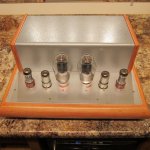
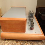
300B Dual Monoblock Stereo Amplifier
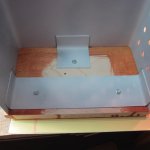
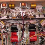
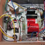
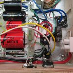
My intention for this post is to share all the details for this amplifier should anyone care to build their own. Schematics and detailed construction pics will be attached.
This is my 19th DIY tube amplifier. The power transformer is shared by both sides, other than that the right/left sides are 100% separate of each other… hence the name Dual Mono Block Stereo.
Some quick specs:
DC heaters for 6SH7’s and 300B’s. Each 6SH7/300B pair used its own heater supply. With this method, the 6SH7 cathode gets biased up to the same voltage as the 300B cathode so keep that in mind if you build your own with a different input/driver valve.
300B’s, 333V, -67V, 67mA, grid choke
6SH7’s, Triode wired, Plate choke loaded, 240V at plate, 10mA
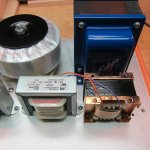
Power supply (separate for right/left side), hybrid GZ34/SS diode bridge rectifier, CLC-RC.
It’s big and heavy.
How does it sound? First impression… this is one of the best sounding amps I’ve build. This amp has way better bass that others I’ve built using the same valves and it seems to be more dynamic and have more of a “punch” than others.
I suspect the plate choke/grid choke and the separate power supplies are responsible for the improved dynamics of this amp compared to other circuits.
More to come...
.
300B Dual Monoblock Stereo Amplifier
My intention for this post is to share all the details for this amplifier should anyone care to build their own. Schematics and detailed construction pics will be attached.
This is my 19th DIY tube amplifier. The power transformer is shared by both sides, other than that the right/left sides are 100% separate of each other… hence the name Dual Mono Block Stereo.
Some quick specs:
DC heaters for 6SH7’s and 300B’s. Each 6SH7/300B pair used its own heater supply. With this method, the 6SH7 cathode gets biased up to the same voltage as the 300B cathode so keep that in mind if you build your own with a different input/driver valve.
300B’s, 333V, -67V, 67mA, grid choke
6SH7’s, Triode wired, Plate choke loaded, 240V at plate, 10mA
Power supply (separate for right/left side), hybrid GZ34/SS diode bridge rectifier, CLC-RC.
It’s big and heavy.
How does it sound? First impression… this is one of the best sounding amps I’ve build. This amp has way better bass that others I’ve built using the same valves and it seems to be more dynamic and have more of a “punch” than others.
I suspect the plate choke/grid choke and the separate power supplies are responsible for the improved dynamics of this amp compared to other circuits.
More to come...
.
Attachments
-
 IMG_2255.jpg850.1 KB · Views: 655
 -
 IMG_2257.jpg731.5 KB · Views: 630
 -
 IMG_2258.jpg499.9 KB · Views: 601
 -
 IMG_2261.jpg735 KB · Views: 620
 -
 IMG_2254.jpg423.3 KB · Views: 589
 -
 IMG_2247.jpg647.3 KB · Views: 260
 -
 IMG_2244.jpg686.9 KB · Views: 326
 -
 IMG_2243.jpg951.4 KB · Views: 357
 -
 IMG_2239.jpg644.7 KB · Views: 347
 -
 IMG_2240.jpg777.8 KB · Views: 290
"6SH7’s, Triode wired, Plate choke loaded, 240V at plate, 10mA"
Could I ask the choke brand and specs?
Could I ask the choke brand and specs?
Last edited:
The plate and grid choke came from this seller on ebay
https://www.ebay.com/usr/vintage_audio_lab?_trksid=p2047675.l2559
Here are the plate choke specs... from the sellers site.
Features of Valab AP200-35 Anode choke
* 50% Nickel iron + 50% Z6 silicon iron lamination.
* 5n oxygen free copper wires was used in coil wiring.
* 14000 turn coils, generating 200H at 120Hz and over 1100H at 20Hz.
*2330Ohm DC resistance
* Weight: 800g each choke, about 2000g after packaging (2 chokes)
Here are the schematics
What's the idea behind the positive feedback to the cathode?
The plate and grid choke came from this seller on ebay
https://www.ebay.com/usr/vintage_audio_lab?_trksid=p2047675.l2559
Here are the plate choke specs... from the sellers site.
Features of Valab AP200-35 Anode choke
* 50% Nickel iron + 50% Z6 silicon iron lamination.
* 5n oxygen free copper wires was used in coil wiring.
* 14000 turn coils, generating 200H at 120Hz and over 1100H at 20Hz.
*2330Ohm DC resistance
* Weight: 800g each choke, about 2000g after packaging (2 chokes)
Thanks
The positive feedback idea is the so called Ultrapath connection. Best explained by John Broskie in tubecad on 31/8/2008.
Zeta4,
Thanks for answering Mark's question about the positive feedback.
I've seen it used in other 300b circuits (WE91 for example)
To be perfectly honest, I can't say if it improves the sound.
Thanks for answering Mark's question about the positive feedback.
I've seen it used in other 300b circuits (WE91 for example)
To be perfectly honest, I can't say if it improves the sound.
It looks to me that the (hopefully) high impedance grid choke lead, is returned to ground through a very low impedance wire that also connects to the input stage cathode.
I would say that any feedback from the grid choke return to the input stage cathode only occurs at very high frequencies, way above any audio frequency.
It's all about making a pretty schematic, to confuse some people.
On the other hand, the cap from the output transformer primary B+ to the output tube filament circuit is just a shorter and more direct connection, versus letting all the currents flow from the power supply B+ through the primary, and returning to ground through the filament's self bias resistor and bypass capacitor circuit ("cathode" circuit) to ground. Instead, the 10uF bypasses some of the current, but ultimately, it still has to return to the B+ supplies ground connection.
There again, a short wire is a much lower impedance at RF frequencies, but not much of a problem at audio frequencies.
Hopefully, there is a much higher capacitance in the B+ power supply, or you are going to be missing the lower bass notes (they will be attenuated).
10uF is 1,000 Ohms at 20Hz; that is too high of a B+ impedance versus the the 2500 Ohm primary. And the 2500 Ohm primar may be much less than 2500 Ohms at 20Hz because of the primary inductance.
Check which are the outer layers of the Onion. Peel them off first. The major problems of the amplifier are not the inner layers of the onion.
Last edited:
6A3sUMMER, thank you for the reply.
Let me try to explain the schematic. I drew the schematic as I actually wired the amp. I try to avoide "ground loops"
The Grid Choke does go to the 6SH7 cathode ground and then to the main ground bus at the 22uf cap, the last cap of the power supply. I wired it this way under the assumption that the Grid Choke is actually part of the input circuit.
The last cap for the B+ is 80uf
The 300B cathode resistor is bypassed with a 30uf cap
I'm open to suggestions if you think the 10uf ultrapath cap does more harm than good.
I can use it for the 300B cathode bias in addition to the 30uf cap.
This amp does not measure very well. I waiting for the amp to burn in a bit before I publish the numbers.
On the other hand, this amp sounds very good just the way it is!
Again, I'm open to any other suggestions that might improve the amp.
-Scott
What's the idea behind the positive feedback to the cathode?
It's for PSU ripple cancelling and it goes back to early Western Electric SE amplifier designs, there should not be much audio present on the supply rail.
The capacitors form a capacitive divider, optimum capacitance ratio is approximately 1/mu+1. (Err to towards a slightly larger overall ratio rather than the reverse)
I've used this in some of my older designs and it can be quite effective. (You can get 20dB or so improvement with care)
Ultrapath is a little different - omitting the second capacitor from cathode to GND. "Ultrapath" originated with Jack Elliano at Electra-print maybe 25 years go.
- Home
- Amplifiers
- Tubes / Valves
- 300B Dual Monoblock Stereo Amplifier