I'm interested in learning more about whether/ how the placement of the open "far end") of a transmission line, in relation to the active drivers, and also in relation to room features such as floor or close-adjacent wall, does or doesn't effect the overall driver/ cabinet 'system's' performance.
For context for my question, I see some designs, for example, the Brines TL designs and 'Pensils' that have the TL open end at floor level.
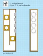
I also see designs like the Jordan 'Eikona' Line Array TL', where the open end of the TL exits upward from the top rear of the cabinet - image attached and also described at: DIY - Eikona Transmission Line Array - E J Jordan Designs
...and even a DIY TL design that wraps up and around with the open end pointing forwards directly above the driver (image attached, from the customer project images at Parts Express' product page for the Tang Band W8-2145
If it's like anything else, I expect that there are pros and cons to each different option, I'm just interested in trying to learn more about what those tradeoffs are for the different locational options for the open end of a TL.
Thanks in advance!
For context for my question, I see some designs, for example, the Brines TL designs and 'Pensils' that have the TL open end at floor level.
I also see designs like the Jordan 'Eikona' Line Array TL', where the open end of the TL exits upward from the top rear of the cabinet - image attached and also described at: DIY - Eikona Transmission Line Array - E J Jordan Designs
...and even a DIY TL design that wraps up and around with the open end pointing forwards directly above the driver (image attached, from the customer project images at Parts Express' product page for the Tang Band W8-2145
If it's like anything else, I expect that there are pros and cons to each different option, I'm just interested in trying to learn more about what those tradeoffs are for the different locational options for the open end of a TL.
Thanks in advance!
Attachments

I'm also curious what people with experience have to say about this. I can imagine folding a TL around all sorts of ways that I've never seen built. How much of that is ease of building vs. acoustics? From what I've read, and a bit of playing around with hornresp, if you're using the TL to extend the bass response you might want the exit in the back bottom to take advantage of the room. And if you're just using it as an acoustic "black hole" for the back wave, probably not enough sound comes out the exit for it to matter. Having the exit next to the driver, I would worry about the delayed sound coming out the exit interfering with the front wave and causing frequency response problems, but that's just conjecture.
Try to get hold of Leonard Audio‘s free TransmisssionLine software. You can play around with all kinds of placements, very educative.The differences in simulation are considerable.
I'm interested in learning more about whether/ how the placement of the open "far end") of a transmission line, in relation to the active drivers, and also in relation to room features such as floor or close-adjacent wall, does or doesn't effect the overall driver/ cabinet 'system's' performance.
Well, to a point you're conflating several matters matters; terminus exit location into the room, and terminus position relative to the line geometry. These are not necessarily synonymous.
-In the case of the former, the basic principles do not change whatever type of vented load it might happen to be (bass reflex or vented box, QW variation, horn or whatever); merely the details thereof. So you are 'simply' dealing with a question of room acoustics and the excitation thereof; all other things being equal, close[r] proximity to boundaries can provide greater excitation or boundary loading, but things are not always equal. Down-venting for example can be used to provide greater damping depending on the gap between the enclosure and the floor / plinth and the materials involved.
-Internal terminus position varies depending on line design. In some cases, this is done with reference to room boundaries, but in many / most, it is taken purely in reference to the enclosure load / alignment, with room excitation a secondary factor.
For example:
For context for my question, I see some designs, for example, the Brines TL designs and 'Pensils' that have the TL open end at floor level.
Actually, they are not. These are mass-loaded quarter-wave enclosures, and technically speaking the duct / vent is slightly offset from the line terminus, not directly at floor level. The duct offset (particularly in the case of Bob's MLTLs and similar enclosures, slightly less so with the pensils, although technically they still have a slight offset) is chosen for reasons of line behaviour.
I also see designs like the Jordan 'Eikona' Line Array TL', where the open end of the TL exits upward from the top rear of the cabinet
This is a totally different type of QW load; it is not an MLTL but a straightforward, untapered QW pipe with roughly a 0.175 driver offset. It's about 88in long, and folded in half to keep the box height to that of a typical floorstander. The line exits at the top because that is where the end of the line is, simple as. You can't move it without changing the design and line behaviour.
...and even a DIY TL design that wraps up and around with the open end pointing forwards directly above the driver (image attached, from the customer project images at Parts Express' product page for the Tang Band W8-2145
I don't have time to reverse-engineer it, but this appears to be a somewhat questionable, straightforward untapered QW pipe that has been folded in such a way to position the terminus beside the driver. This may simply be for convenience of folding layout depending on what the design is meant to be used for and how it is placed; if it's laid on its side and / or rammed into a console, there isn't really much option about locating a terminus on the front panel for obvious reasons. And so on.
Thank you VERY much Scottmoose! I learned a great deal from your response. Do you have any broad reactions to whether there are any big pitfalls of the Jordan QW design's general layout?
Reason I ask is that I'm interested in eventually trying to design and build something "W.A.W. -ish" with the 'woofer assist' consisting of four Audible Physics 6.5" drivers (4 per speaker) and the Jordan layout looks intriguing. In what I am envisioning, the "wideband" portion would have its own distinct compartment above/ separate from the woofers, with the lengths (overall size of the system and of the QW) juggled accordingly to both the A/P drivers' parameters and the additional space for the wideband chamber above the woofers' QW section. Trying to get a very general sense of whether that type of layout is worth considering, or a fool's errand...
Thanks!
Last edited:
Well, to a point you're conflating several matters matters; terminus exit location into the room, and terminus position relative to the line geometry. These are not necessarily synonymous.
-In the case of the former, the basic principles do not change whatever type of vented load it might happen to be (bass reflex or vented box, QW variation, horn or whatever); merely the details thereof. So you are 'simply' dealing with a question of room acoustics and the excitation thereof; all other things being equal, close[r] proximity to boundaries can provide greater excitation or boundary loading, but things are not always equal. Down-venting for example can be used to provide greater damping depending on the gap between the enclosure and the floor / plinth and the materials involved.
-Internal terminus position varies depending on line design. In some cases, this is done with reference to room boundaries, but in many / most, it is taken purely in reference to the enclosure load / alignment, with room excitation a secondary factor.
For example:
Actually, they are not. These are mass-loaded quarter-wave enclosures, and technically speaking the duct / vent is slightly offset from the line terminus, not directly at floor level. The duct offset (particularly in the case of Bob's MLTLs and similar enclosures, slightly less so with the pensils, although technically they still have a slight offset) is chosen for reasons of line behaviour.
This is a totally different type of QW load; it is not an MLTL but a straightforward, untapered QW pipe with roughly a 0.175 driver offset. It's about 88in long, and folded in half to keep the box height to that of a typical floorstander. The line exits at the top because that is where the end of the line is, simple as. You can't move it without changing the design and line behaviour.
I don't have time to reverse-engineer it, but this appears to be a somewhat questionable, straightforward untapered QW pipe that has been folded in such a way to position the terminus beside the driver. This may simply be for convenience of folding layout depending on what the design is meant to be used for and how it is placed; if it's laid on its side and / or rammed into a console, there isn't really much option about locating a terminus on the front panel for obvious reasons. And so on.
Scott, do you have an analysis of the DTQWT (any version)? It uses a bottom firing TQWT and I think he might be on to something with the design - using a single port on the bottom for both the LF and MF/HF ranges.
Scott, do you have an analysis of the DTQWT (any version)? It uses a bottom firing TQWT and I think he might be on to something with the design - using a single port on the bottom for both the LF and MF/HF ranges.
Well first, I'd say in deference to Troels that while I can offer an objective critique (not 'criticism') of the design approach according to my own understanding and preferences, the DTQWT is popular and well-liked by its builders, and I emphatically do not presume to tell people what they should do or like.
That caveat clearly stated, we should note that the DTQWT is a 2 1/2 way design, which happens to use dissimilar supporting woofers. The forward-firing 8in midbass is used as just that: a midbass, there is no high pass. I note this because the woofers share the same volume. The load in this sense is immaterial, and by my lights, it would be more problematical were the 8in midbass to be high passed as there is inevitably some cross-modulation, and at least when run wide open in the LF, it's doing some work itself which may compensate a little for that. While there is precedent aplenty for dissimilar drivers in the same volume (Wilson et al IIRC), it's not an approach I tend to gravitate toward for that reason.
Moving on to the load, there is no mid or HF line. The tweeter, like all dome tweeters, is a sealed back unit, and the 8in midbass as noted is not high passed. It's a bass enclosure; a bifurcated or Y shaped [single] tapped horn to be precise, albeit with initial dissimilar (in some versions) expansions, which presumably is primarily a consequence of providing clearance for the driver motors rather than for acoustic reasons per se. Vented back loads are only useful in the LF anyway or GD becomes excessive. From the perspective of design, I have certain issues with this dissimilar expansion since it in effect results in dissimilar tuned pipes that are combined (near the top of the box), and without very careful design, that can cause some problematic load effects; it's more or less the same as high performance header & exhaust design in that sense as the box is a standing-wave generator & when you combine differential loads, things get a mite complex. Lynn Olson found that in early versions of the Ariel, particularly toward the top end of the box passband; his solution worked at solving that particular issue, although was somewhat more complex than it actually needed to be (he could have just removed a couple of panels, but a 1/4 century of hindsight is a wonderful thing 😉 ). So in that sense -not how I would prefer to do it, given the option. Which isn't to say it does not, or cannot, work, just that the physics and operating behaviour are more complex than they might appear from a simple design routine or test.
In terms of down-firing, plenty of boxes of this type about, and that needs no real assessment. They can provide a degree of damping / mass loading depending on the gap to the floor / plinth, and depending on application can work well; lots of DIY and commercial examples of such speakers out there.
Last edited:
Scottmoose- I'd be very interested, please, if you have any thoughts on any major downsides or pitfalls on the design/layout of the Jordan 4-driver QW arrangement? Thanks very much
As noted, I do not much like offering theoretical critiques of other people's work, so I'd ask this to be kept in mind.
In terms of the line itself, there isn't all that much to say about it: as a type, it is a straightforward untapered QW pipe. By definition the array configuration provides some physical driver offset (a touch less than my quick stab above). The cross-section / total cabinet volume is a bit small by my lights given the driver Q and volume compliance, although that may make near-boundary positioning easier. Re the short array, the advantages & compromises of such configurations are well known, and others have also taken this approach. Some clearly like it from the feedback on the site; no doubt others will not care for it as much, like any loudspeaker. There has yet to be one that is all things to all people.
In terms of the line itself, there isn't all that much to say about it: as a type, it is a straightforward untapered QW pipe. By definition the array configuration provides some physical driver offset (a touch less than my quick stab above). The cross-section / total cabinet volume is a bit small by my lights given the driver Q and volume compliance, although that may make near-boundary positioning easier. Re the short array, the advantages & compromises of such configurations are well known, and others have also taken this approach. Some clearly like it from the feedback on the site; no doubt others will not care for it as much, like any loudspeaker. There has yet to be one that is all things to all people.
Last edited:
Thanks very much Scott, I appreciate your sharing your insights, and also respect your circumspection.
Try to get hold of Leonard Audio‘s free TransmisssionLine software. You can play around with all kinds of placements, very educative.The differences in simulation are considerable.
Indeed! Hornresp can do a basic offset, which is usually sufficient.
GM
- Home
- Loudspeakers
- Full Range
- Transmission line - exit placement effects?