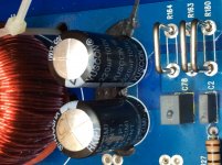
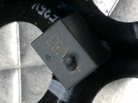
Hey guys, this amp had the caps on the output blown electrolytic and Mylar, I’m however unable to identify the Mylar (one of), does anyone have any data on the unidentifiable part? It’s 4??J63 C78.
And what would cause the caps to be blown the electrolytics are 100v. Any suggestions?
And what would cause the caps to be blown the electrolytics are 100v. Any suggestions?
Attachments
R82DC3470DQ60K -
DC Film Capacitor, 0.47 µF, 63 V, Metallized PET Stacked, ± 10%, R82 Series
What would be the part number written on it?
And why is it at 63volts when the other caps across the output is rated at 100v?
I really do not have a schematic for this amp, and the part is burnt, I can’t recognize the numbers, however I see another amp of different type that has a 474J100 in that similar location (series with a 22K resistor).
How do you know it’s a 470 and not a 474? Do you have the schematic for the amplifier?
How do you know it’s a 470 and not a 474? Do you have the schematic for the amplifier?
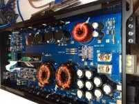
Post a photo of the audio driver board. That may help match it up with a similar amp.
I'd guess 474 because most amps tend to use something like a 1uf film cap there... and because (may be my imagination) that I see the leg of a 4 under the bubble.
I'd guess 474 because most amps tend to use something like a 1uf film cap there... and because (may be my imagination) that I see the leg of a 4 under the bubble.
No Mr Babin, it wasn’t your imagination. I’ve put it under the microscope and I see the foot of the seven and bottom of the four.
Could an over oscillation cause from the driver board to produce frequencies that blew the caps?
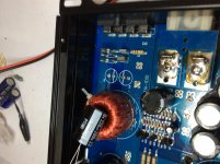
Could it be reversed polarity also, as some Mylar caps are looking swollen and melted on the B+ to GND and B+ to chassis GND near the power terminal end?
Could an over oscillation cause from the driver board to produce frequencies that blew the caps?
Could it be reversed polarity also, as some Mylar caps are looking swollen and melted on the B+ to GND and B+ to chassis GND near the power terminal end?
Attachments

What are the numbers on the two driver board ICs?
Almost without exception, the failure of these parts is due to a shorted output filter inductor (possibly intermittently).
Almost without exception, the failure of these parts is due to a shorted output filter inductor (possibly intermittently).
The numbers are IR2010S and 74HC02D.
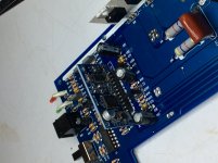
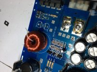
The output inductor is a bit wiggly, but I don’t see any chafing under the anchored wraps on the coil itself, no blackening or arcing.
The output inductor is a bit wiggly, but I don’t see any chafing under the anchored wraps on the coil itself, no blackening or arcing.
I don't see anything with that combination.
If that inductor isn't almost perfectly rigid, I'd suspect that it has shorted windings. After you get the amp working, monitor the idle current and move the inductor to see if idle current changes when you move it.
I think that cap is a .47uF It's not critical. It's just to pull the last bit of noise off of the output signal.
If that fixative is the beige stuff that's turned dark/conductive/corrosive, it needs to be removed. If it's black and still rubbery, it's OK.
Will the amp produce at least clear audible sound if the capacitors that’s arranged in a bipolar topology (ground pins connected with + side across output) is removed?
I’m really getting some weak and scratchy audio nothing with power as even how the amp should play.
And twisting of the inductor didn’t increase the idle current even with audio.
I’m really getting some weak and scratchy audio nothing with power as even how the amp should play.
And twisting of the inductor didn’t increase the idle current even with audio.
Attachments
Last edited:
You're unlikely to get clean audio without the caps.
The checking of the inductor needs to be done with the caps in place.
Assuming that you don't have replacement caps... Just wire in any capacitors (of similar value) you have in series like the originals and solder the remaining two capacitor terminals to the board on the outer two terminals for testing.
I’ve replaced all the physical blown caps, and stabilized the output inductor (it wasn’t shorted and the amp is just a few weeks old), the customer says it only played for a time and it’s blown the caps again, what could be causing it?
Did you push/pull/twist the inductor while the amp was powered up to see if anything (generally idle current) changed while doing that?
There is virtually nothing else that can do that, assuming that the amp is oscillating at anything near the normal operating frequency (probably about 80kHz or higher).
What's the rail voltage in the amp?
There is virtually nothing else that can do that, assuming that the amp is oscillating at anything near the normal operating frequency (probably about 80kHz or higher).
What's the rail voltage in the amp?
The rail voltages are +/-78
The idle current is 1.2amps nothing changed when twisting of the inductor.
Does it want higher capacity caps? The originals are 100v/220uf 105^C the replacement was the same except 85^C now I have 200v/220uf at 105^C.
***How do I test the operating frequency?
The idle current is 1.2amps nothing changed when twisting of the inductor.
Does it want higher capacity caps? The originals are 100v/220uf 105^C the replacement was the same except 85^C now I have 200v/220uf at 105^C.
***How do I test the operating frequency?
Last edited:
Did the 63v caps heat up when you tested it before returning it?
How long did you test?
Did you test to intermittent output clipping when you tested?
How long did you test?
Did you test to intermittent output clipping when you tested?
None of the poly film caps are damaged on this return I used 100v on all those just the electrolytic caps burst this time, I only tested for audio I didn’t do a lengthy test.
I could if remembered correctly I think during my short test, the electrolytic caps was a bit warm but I was thinking that maybe I’ve just soldered them in.
I could if remembered correctly I think during my short test, the electrolytic caps was a bit warm but I was thinking that maybe I’ve just soldered them in.
Test again, driving the amp to clipping (intermittently) with music. Do the caps get hot?
Most amps use caps that are 2x the rail voltage. I don't think that's necessary but something greater than 63 ight be needed. Were the 63v caps original?
Most amps use caps that are 2x the rail voltage. I don't think that's necessary but something greater than 63 ight be needed. Were the 63v caps original?
I can't tell the size but they look small. The 220uf@200v I used were 22mm dia and 25mm long. Are those close to that.
- Home
- General Interest
- Car Audio
- SoundStream BXA1-7500D blown caps