Hi diyAudio friends,
I have an issue with a Sony TA-F35 Integrated Amplifier: It is mute for the first time (I have bought it new...).
Now, when I switch the power on, I ear no more the habitual "click" before starting but the indicators light on.
I have some electronic knowledge and tools like multimeter, soldering iron.
Which are the relevant tests to do ?
I hope that you could help me for fixing.
Many thanks
Michelnou
First you need the service manual, which is HERE
It sounds like it's locked in protection mode.
First a note of caution... If you've never done this before, you may want to consider taking your unit to a trained technician. There are voltages inside that can be very dangerous.
Connect your meter's negative test lead to chassis ground.
With the amplifer turned on, no input, no speakers...
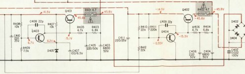
First thing check Your supply voltages ... +45 and -45, +14.5 and -14.5, at the test points indicated on the schematic. Make sure they're all correct. See the attachment below.
Next you need to check for DC offsets at the amplifier outputs on each channel. This should be very nearly 0 volts. I marked the test point on the attachment below.
let us know what you get...
It sounds like it's locked in protection mode.
First a note of caution... If you've never done this before, you may want to consider taking your unit to a trained technician. There are voltages inside that can be very dangerous.
Connect your meter's negative test lead to chassis ground.
With the amplifer turned on, no input, no speakers...
First thing check Your supply voltages ... +45 and -45, +14.5 and -14.5, at the test points indicated on the schematic. Make sure they're all correct. See the attachment below.
Next you need to check for DC offsets at the amplifier outputs on each channel. This should be very nearly 0 volts. I marked the test point on the attachment below.
let us know what you get...
Attachments

Last edited:
Sony RA-F35 issue
Douglas,
Thank you for your answer.
Before to start your tests program, I bring some additional informations.
In some cases, when I switch the power on, the relay click and the amplifier work correctly during some minutes; then the sound disappears and comes back after 10 to 20 seconds.
When the amplifier seems to work correctly, I have noticed that if I turn the Balance button towards right channel, I ear the relay clicking and the sound disappear on the both channels during 10 to 20 seconds.
Maybe that these additional informations modify your tests suggestions.
Thanks you again for your help
Douglas,
Maybe that these additional informations modify your tests suggestions.
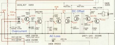
They might... but looking at the schematic I see only 3 things that would cause that relay to drop out... DC offsets, loss of AC power or overcurrent. I think it's best to explore those causes first.
These checks can all be made from component leads on top of the board. So lets not tear it down until we have a reason to...
Last edited:
When the amplifier seems to work correctly, I have noticed that if I turn the Balance button towards right channel, I hear the relay clicking and the sound disappear on the both channels during 10 to 20 seconds.
Now that's curious.
Observing the circuit around the balance pot, it is followed with a subfilter and a NJM4559D opamp. This sub filter, when switched on, is switching two capacitors of different value and making in series. One of them (C203/253) is a 1µ/50V polarised cap.
If, by some reason, ths cap-chap is degraded in quality over time, it might become acting other than a cap. 1/2 IC 201 (*) will notice and will shift in the operation point, or can be pulled into a undefined state, causing the supply to drop considerable (check pin 1 and 8 when no sound). As the first stage of the main amp is on the same rail (both channels!), the protection circuit kicks in releasing the output relays.
(*) The other 1/2 of this IC is in use for the other channel.
Just measure the dc voltages of all pins on this IC, but be carefull!!! Avoid shorting pins after a few cups of café noir.
Now that's curious.
Observing the circuit around the balance pot, it is followed with a subfilter and a NJM4559D opamp. This sub filter, when switched on, is switching two capacitors of different value and making in series. One of them (C203/253) is a 1µ/50V polarised cap.
Not likely to cause a protection trigger ... Note that the output of that op amp is AC coupled into the power amplifier.
Plus the 14.5 volt rails are not monitored.
Last edited:
It is not through the ac coupling C301/351....the output of that op amp is AC coupled into the power amplifier...
But Q301 (351) is on the +14.5 rail, so when havoc occurs there, this stage will shift too. Hence the reasoning.
It is a possible cause, not neccessarely the cause!
It is not through the ac coupling C301/351.
But Q301 (351) is on the +14.5 rail, so when havoc occurs there, this stage will shift too. Hence the reasoning.
It is a possible cause, not neccessarely the cause!
Lets keep that in mind for later, if the trail leads us there...
The 14.5 volt rails are not monitored... as in can't trip protection.
I'm attaching a snip of the protection circuit. I've marked the functions of the various sections in Blue.
First lets be sure we have good power supplies and no DC offsets.
Attachments

Last edited:
...The 14.5 volt rails are not monitored... as it can't trip protection...
It can, even if it is not monitored. Q301 (351) can go beserk causing large dc offset at the output triggering the prot circuit.
Granted, first things first. Let's await results from Michelnou.
It can, even if it is not monitored. Q301 (351) can go beserk causing large dc offset at the output triggering the prot circuit.
When there is reason to walk backwards through an amplifier to find the cause of a problem we can check it out then. As it is right now we have no idea if there even is a DC offset. Wild speculation fixes nothing.
90% of the time it's a bad output transistor.
Lets not get ahead of ourselves.
Granted, first things first. Let's await results from Michelnou.
Yes, please...
Last edited:
Hi Guys,
I thank you for your advices and your documents.
Don't be angry with me but I need some time to progress.
Cordially
Michelnou
I thank you for your advices and your documents.
Don't be angry with me but I need some time to progress.
Cordially
Michelnou
Hi Guys,
I thank you for your advices and your documents.
Don't be angry with me but I need some time to progress.
Cordially
Michelnou
That's fine. Take as long as you need.
Hi diyAudio friends,
I need some complements before starting tests ,
- I have understood that all voltages are direct type (DC). Is it OK ?
- I have understood that voltage checking must be carried out with the amplifier disconnected of any sources and loudspeakers. Is it OK ?
- I should want to know if the points of measurement (xy Volts) on the upper face of the board are marked ?
I thank you for your help
Michelnou
Hi diyAudio friends,
I have carried out the voltage measures today.
I have observed durig the tests (under voltage) that the relay don't stop to click after heating.
First phase : Q401, Q402, Q403, Q404 measures
Q401 : emitter 15,27 V, collector 47 V
Q403 : emitter 5,84 V, base 6,4 V
R401 : 47,2 V
Q402 : emitter -14,98 V, collector -47,7 V, base -15,6 V
Q404 : base -0,58 V, collector -15,6 V
R402 : -48 V
Second phase : Q306, Q307 measures
Q306 : base 0,48 V, collector 46,6 V
Q307 : base -0,79 v
R318 : delta V = 0 V
Third phase : Q405 to Q411 measures
Q405 : base 46 V, collector 0 V, emitter 47,3 V
Q406 : base 0,0003 V
Q407 : base -0,86 V, collector 1,4 V
Q408 : base -0,08 V, collector 1,4 V
Q409 : emitter -0,08 V
Q410 : emitter 0,73 V, collector 0,79 V
Q411 : base 0,73 V, collector 0,06 V
Thanks for your help
Michelnou
Hi diyAudio friends,
- I have understood that all voltages are direct type (DC). Is it OK ?
Yes, DC voltages measured to ground, unless we note otherwise.
- I have understood that voltage checking must be carried out with the amplifier disconnected of any sources and loudspeakers. Is it OK ?
Yes. Powered on, with nothing hooked up to it. Testing in isolation.
- I should want to know if the points of measurement (xy Volts) on the upper face of the board are marked ?
No they won't likely be marked. The way to get at them is to use the schematic to locate a nearby part... a resistor, usually, and touch your probe against it's legs (wires) from above.
For example with the thumbnail I gave you for DC Offset... look at the schematic, note that point is between R316 and R317 also R318 ... if you locate any of those parts on the board, you can use your probe on their legs as a test point. The other channel will have a similar point where you can probe it.
Let me caution you one more time... There are voltages inside that can be dangerous. There is also the risk of damaging the amplifier, further, if not careful. I'm happy to steer you through this, but if you aren't feeling confident with this and/or you've never done this before, you might want to consider taking your amplifier to a qualified technician for service. It could turn out to be the least expensive option.
Last edited:
Hi diyAudio friends,
I have observed durig the tests (under voltage) that the relay don't stop to click after heating.
I'm sorry, can you clarify... is the relay pulled in, dropped out, or clicking back and forth repeatedly. This is important information as it might indicate a bad relay.
The the power supply readings look okay.
So lets do some double checks on the protection circuit next...
You noted an erroneous reading on the base of Q405 ... Looking at the schematic, I would say this is actually an error on the schematic and your readings are correct. The base of that transistor is fed by D407 and D406 which in turn monitor R413 and R414. Both should sit at nearly the rail voltage unless there is a problem with too much current being drawn. So lets double check that to be sure... Take readings to ground from the cathodes of D407 and D406, both should be within a volt or so of the positive rail.
Next, on the pcb locate R423 and R422. If you follow the schematic you will see these resistors monitor the DC offset from the two amplifiers... I need readings from both sides of both resistors. Reading to ground, you should get almost 0 volts on all 4 points. Stay with each reading for a good few seconds to be sure they are stable.
Finally we need to check the AC monitor. This is fed with D408 through R418. Take a reading on the anode of D408. Again stay with this for a few seconds to be sure it's stable. Now take a reading from the cathode side... this will be an AC reading.
Finally lets check the relay itself. On the schematic you will find D409, which is directly across the relay coil. Take a reading from both sides of this diode and stay with it for a few seconds to be sure it's stable.
Once we are sure of the basics... we can move on to checking the sound problems you've noted.
Attachments
Hi,
I have read with interest your analysis and your new suggestion of measures.
Concerning D409 measures, is it a voltage measure between anode and cathode or a voltage measure between each point and the ground ?
Thank you
Michelnou
I have read with interest your analysis and your new suggestion of measures.
Concerning D409 measures, is it a voltage measure between anode and cathode or a voltage measure between each point and the ground ?
Thank you
Michelnou
Hi from France,
Concerning the relay performance, I have listened to the amplifier (with different sources) during 1 hour. I have observed more than 20 clicks with sound interruption during this time. Most of the time, these interruptions last 1 second, rarely it can last 4 to 5 seconds. I have observed that pushing Loudness button produce click and interruption. I have not observed clicking back and forth repeatedly.
D406 cathode : 47,1 V
D407 cathode : 46,7 V
R422 : delta V = 51,5 mV; -26,9 mV and -83 mV to ground
R423 : delta V = 50 mV; -135 mV and -83 mV to ground
D408 anode : -3,82 V DC
D408 cathode : 20,1 V AC
I wait your answer to carry out the measures on D409.
Very soon
Michelnou
Hi,
After the voltage measures, I have removed the sheet metal under the amplifier.
I have discovered a welding point oxidized. One of the legs of the C312 capacitor is eroded by oxidization.
Can you tell me if this capacitor 10 microF/50V is polarised (its symbol is not 2 parallel segments).
Thank you
Michelnou
It probably is - the stripe on the capacitor's jacket denotes the (-) side. Should be connected to ground.
If the leg is corroded, chances are the capacitor has leaked. Cleaning with isopropyl alcohol after unsoldering required.
BTW, when replacing, I'd suggest a 63 V or maybe even 100 V part - looks like it has to sustain 45.8 V.
If the leg is corroded, chances are the capacitor has leaked. Cleaning with isopropyl alcohol after unsoldering required.
BTW, when replacing, I'd suggest a 63 V or maybe even 100 V part - looks like it has to sustain 45.8 V.
Last edited:
- Home
- Amplifiers
- Solid State
- Sony TA-F35 issue